Quick Start Guide for Arduino Uno Rev3
Introduction
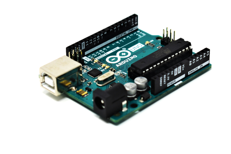
The Arduino Uno Rev3 is one of the most popular development boards on the market due to it’s detailed documentation, wide variety of projects and code, and a strong community. What makes it even more appealing is that it’s open source. That’s right, all of the hardware and software is available to access for free. You can dig into the schematics and even design your own board using it as a reference.
The Uno Rev3 is used among engineers and scientists, but it is mainly targeted towards beginners who are just starting to learn how to code and use a microcontroller. It can be implemented in areas such as automation and control, data acquisition, monitoring, Internet of Things (IoT), and much more.
Here’s what you need to get started:
- Arduino Uno Rev3
- Arduino IDE (we discuss this in the next section)
- Type A to Type B USB Cable to power and program the board
- Laptop or Desktop running Windows, MacOS, or Linux
- FuelCan (optional)
Arduino Integrated Development Environment (IDE)
The Arduino IDE is used to program the board so we can actually do something with it. When you first power up the board, it won’t do anything since we haven’t programmed it just yet. First, you’ll need to head to Arduino’s official website to download the software. Choose the right install based on your operating system (OS). For example, if your laptop is running a Windows OS, you’ll want to choose the Windows Installer. The download takes up roughly 482MB of data on your computer and should take under 10 minutes to finish installation. If you don’t want to have a copy of the software on your laptop, another option would be to use the Arduino Web Editor. This runs in the Arduino Cloud allowing you to save your sketches in the cloud and you’ll always be using the most up-to-date version.
If you decide to download the IDE to your computer, you’ll have to manually install the latest version every time there is a new release. It really depends on your preference of which to use – they both do the same exact thing.
Once you complete the installation process, go ahead and open up the IDE, if it doesn’t start automatically. The IDE is shown below.
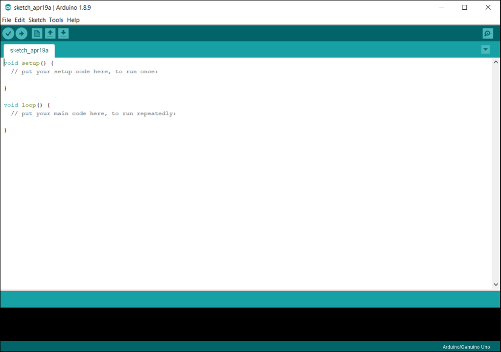
The default sketch (program or code that runs on the Arduino) contains two main functions void setup() and void loop(). These must be in every sketch or you will get an error when you go to upload your sketch. The setup() function executes once, while the loop() function will run forever, when the board is powered on, that is. In the setup() function, you will declare pins as input or output or set the data rate for a serial terminal, for example. Don’t worry if this doesn’t make sense. We will go through an example to clear things up.
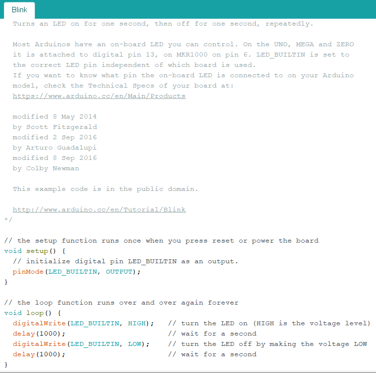
One of the best things about Arduino is that there is a plethora of example code and libraries to use within the IDE. To look at the example code, go to File -> Examples. You’ll see things like Basics, Digital, Analog, Communication, etc. Let’s start in Basics and open up the Blink example. The code is shown below for reference. This code blinks the built-in LED on the Arduino. I encourage you to read the comments denoted by // and try to understand what is going on. Otherwise, we’ll further discuss this in Section 5.
Hardware
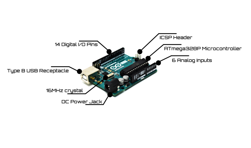
Before diving right into the code, I like to take a look at the hardware on the board or in the schematics to see what is available. If you understand the hardware, you will be able to write much more efficient software. You will also be able to determine if the board you’re using will be sufficient for your design. The Arduino Uno Rev3 has an ATmega328P microcontroller which is the brain of the board. The microcontroller is used to run the software you write in the IDE. It constantly takes in data from it’s surroundings and reacts accordingly. This reaction could be controlling an actuator to move a certain distance or activating a relay to turn on a high-powered motor.
The microcontroller has a certain number of pins (in this case, 28 pins), each with a different function. For example, a pin could be used as input or output, as Pulse Width Modulation (PWM), or as a communication signal for I2C, SPI, or UART. It all depends on how you specify the pin in the setup() function. More specifications about the microcontroller are listed in the image below. I won’t be covering the different types of memory the microcontroller has such as flash, SRAM, and EEPROM since this is a Quick Start Guide.
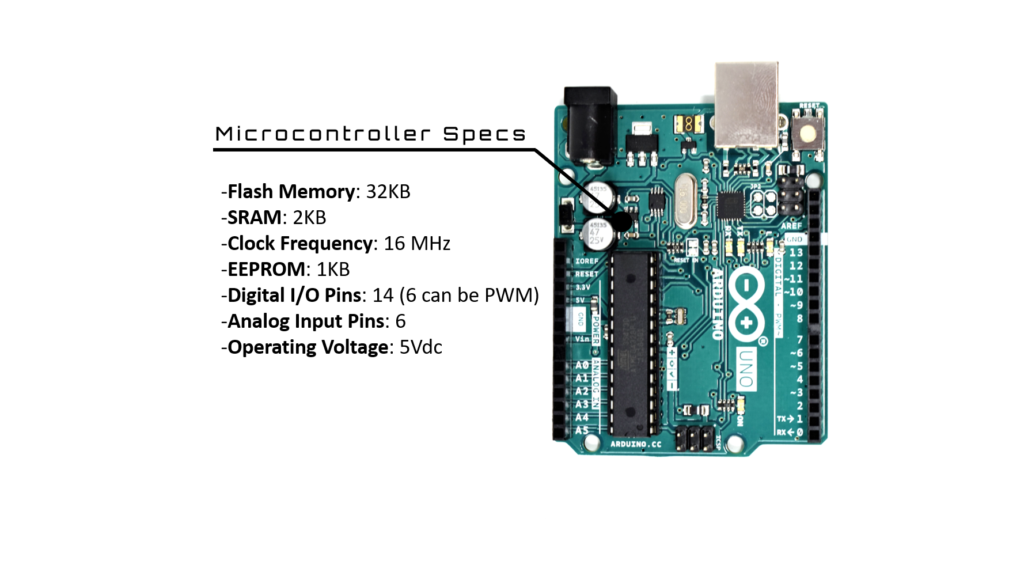
The Arduino has other peripherals, hardware, and components connected to the microcontroller such as voltage regulators (the Arduino runs at 5Vdc), Atmel 16U2 (this chip manages the USB connection and removes the need for an external programmer), 16MHz quartz crystal (provides clock signal for the microcontroller), female header pins (gain access to the pins on the microcontroller), ICSP header (another method available to program the Arduino), Type B USB receptacle (provide power and data), DC power jack (provide power), capacitors, and resistors, as outlined in the image below.
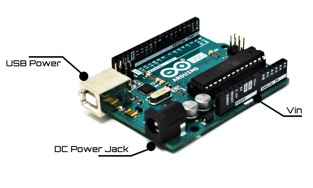
Power Options
There are three ways that you can power the Arduino: 1) using the Type B USB receptacle, 2) using the DC Power Jack, or 3) using the Vin pin. If you’re using the USB receptacle, you can plug it into your laptop to power it. Use caution though – the USB port on your laptop can only provide up to 500mA of current so you may or may not have enough power for your connected sensors or actuators. If you’re using a FuelCan, you do not have to worry about this since it can provide up to 2.5A of current.
When using the DC power jack, you may still have to have the USB cable plugged in if you need to program the Arduino. If you already programmed the Arduino, then you can power it via the DC power jack. The recommended AC/DC power adapter is a 9Vdc output, but the output can vary from 7 – 12Vdc. The DC input range for the Vin pin is also 7 – 12Vdc. If you have more than one supply hooked up to the board, i.e., USB and DC power jack, it will choose the external power supply automatically since it has a higher voltage.
First Example Project
I’m going to continue building off from Section 2 since we already have the example code for Blink opened up. Let’s take a closer look at the setup() function. Here, we specify the LED_BUILTIN pin (attached to digital pin 13) to be an output since we want to provide a voltage for the LED to turn on. If it was set as an input, it won’t work – it also doesn’t hurt anything. Next, we have the loop() function where we turn the LED on, wait 1000 milliseconds, turn the LED off, and wait another 1000 milliseconds. If we don’t have the delay, you won’t be able to see the LED blinking since it’s too fast for the human eye to see.
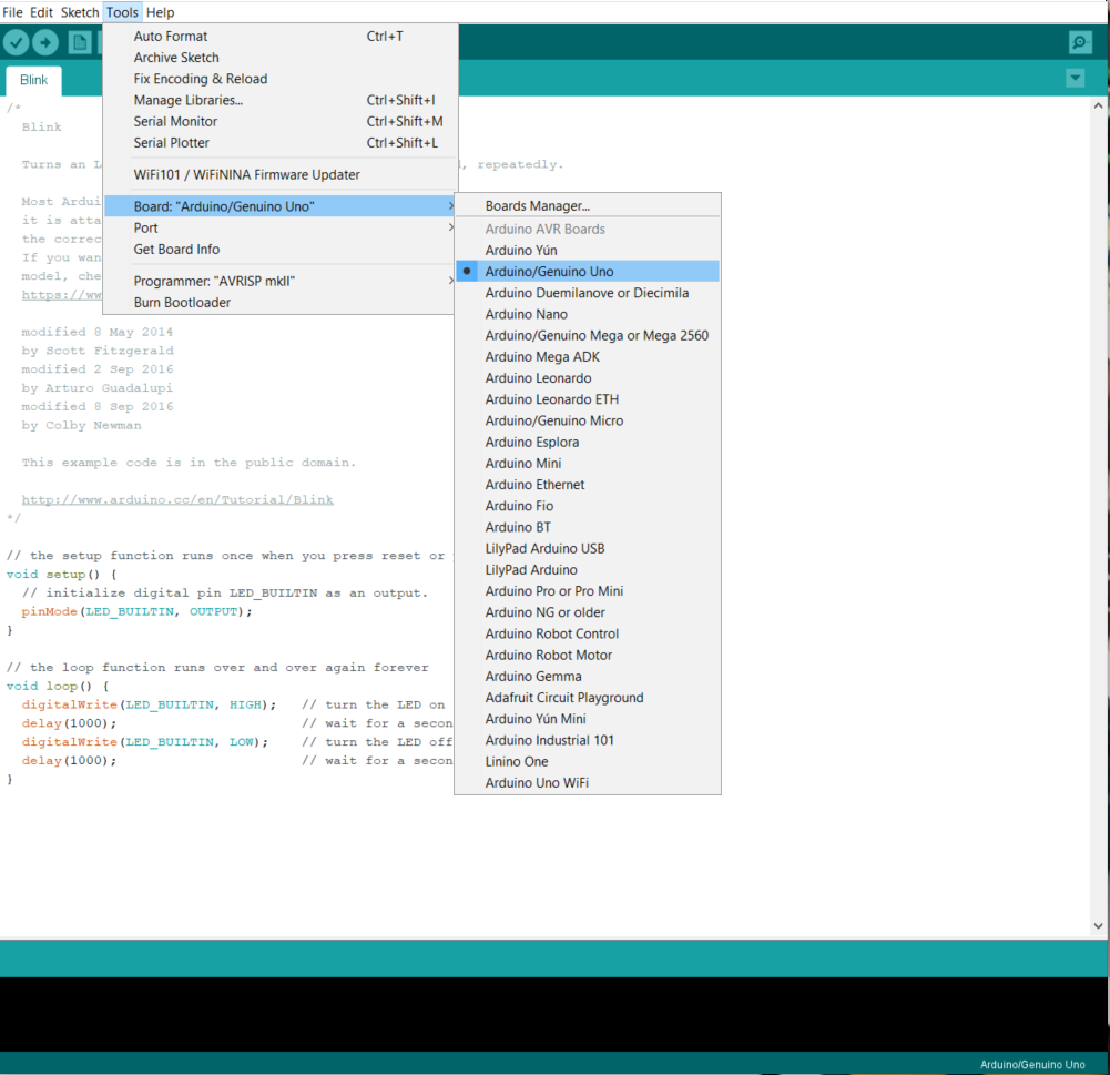
Now that we know what the program will do, we now have to load the sketch to the microcontroller’s memory so it can execute. To do this, plug the USB cable into the Arduino and a USB port on your computer. You should see the ON LED light up. Next, go to Tools -> Board and select Arduino/Genuino Uno as shown in the below image.
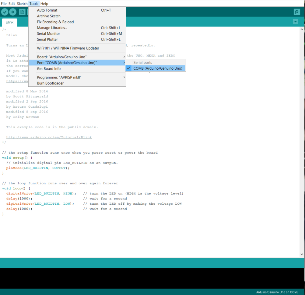
After you select the board, we have to choose the correct COM port. If the board does not show up, try a different USB port on your laptop. If it still doesn’t show up, try restarting the Arduino IDE. In my case, the board got mapped to COM8 port, as shown below.
We now have the board and COM port specified. All that’s left to do is upload the sketch to the Uno Rev3. To do this, click the Upload button which is the right-facing arrow, just under the Edit tab.
NOTE: Since we know this code works, we skipped the Verify step. If you are writing your own code, click Verify (check mark button) first to make sure there are no errors within your sketch, and then click Upload.
If the sketch was uploaded correctly, you should now see the LED blinking! Exciting, right? Want to play around with the sketch some more? Try increasing the delay to blink the LED every 5 seconds!
Further Reading
The LED example is one of the simplest projects to get working. However, don’t underestimate its power. The LED can be used for debugging, signaling, and satisfaction. What do I mean by these three uses? Let’s say you’re trying to pinpoint exactly where your code is getting hung up. You have 3 functions that run sequentially but it’s not running the 3rd function. You should ask yourself “is function 1 and 2 finishing, am I able to get into function 3?” One way to tell is to use the LED. Once you get inside the function, turn the LED on, then when you exit the function, turn the LED off. Make sure you have a 1 second delay in between turning the LED on and off. Otherwise, the function could execute too quickly and you won’t even see the LED cycle.
A common use of LEDs is to place them on data lines. For example, say you are using UART which consists of a TX and RX signal. This will help you see data being sent back and forth. If the LED on the RX line isn’t lighting up, you know that something is wrong in the code or something wasn’t configured correctly.
It’s always satisfying to see an LED light up. That means that the code is working correctly or you are one step closer to squashing that bug that’s causing errors.