Quick Start Guide for FuelCan

NOTE: this is not a substitute for the FuelCan User Guide. Please read the entire FuelCan User Guide before you get started.
Introduction
The FuelCan-910 is a tool for education and rapid prototyping. Our goal was to make a platform that is very easy to use, but also very powerful, so that the end-user does not have to spend much time figuring out how to use it. In this Quick Start Guide, we will cover what’s included within the FuelCan, power options and distribution, mounting boards in the prototyping area, how to install and remove a Canister from the FuelCan’s female 4×26-pin connector, how to create a Canister stack, pinout of the 4×26-pin connector, and the external connectors.
What's Included
The FuelCan-910 comes with a variety of subassemblies, parts, and cables. Since there are so many parts we even have a check list that we go through for each FuelCan to make sure we didn’t miss anything before shipping it. There is a small chance that we may have missed something. If that is the case, please send us an email and we’ll ship it to you, free of charge.
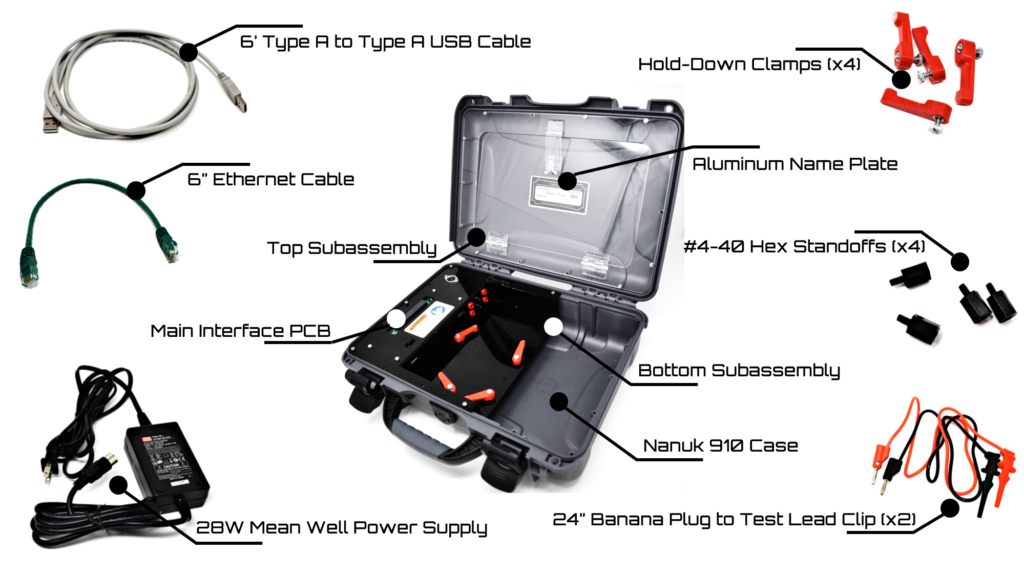
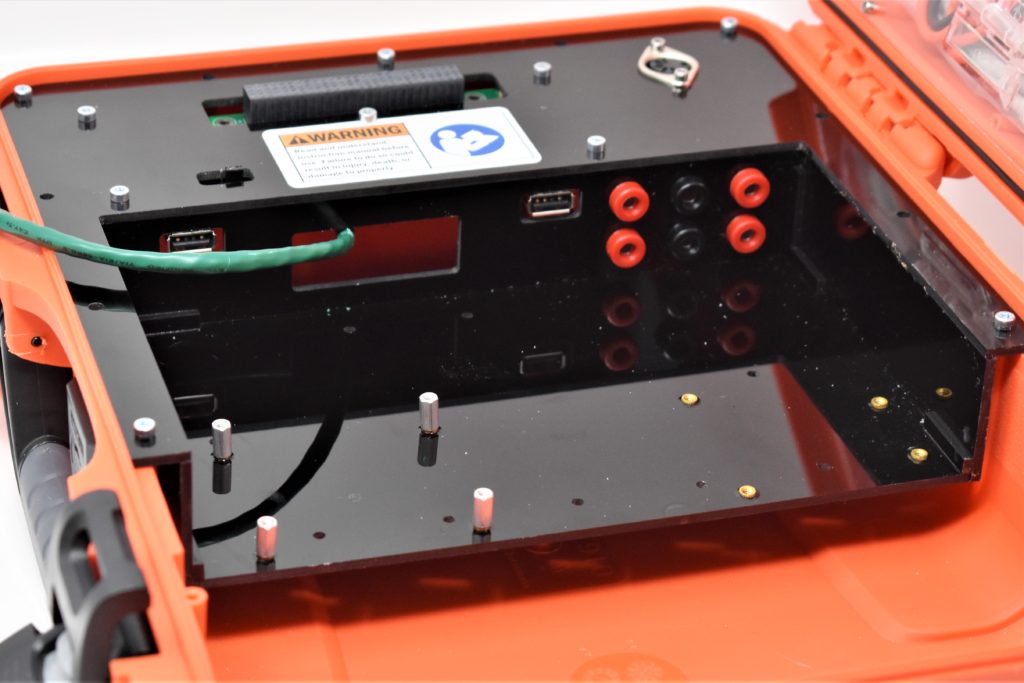
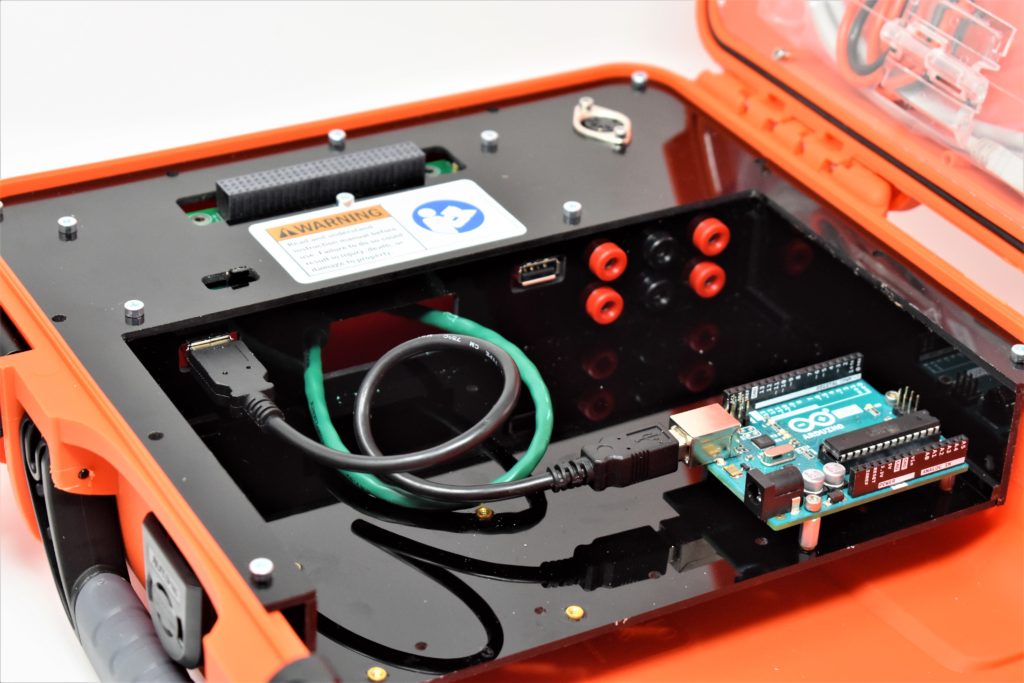
An image of what’s included is above. A detailed list of each subassembly, part, and cable is below:
- Nanuk 910 Case: this case seamlessly integrates everything that’s included. It is rugged, lightweight, and waterproof. You don’t have to worry about the elements encountered when carrying your gear.
- Top Subassembly: this is for the top storage compartment. It consists of an easy-to-open hatch and is used to store cables, heat shrink, small sensors and modules, and bags full of passive components.
- Bottom Subassembly: this is where the Main Interface PCB, 5-pin DIN connector, and Banana jacks are mounted.
- Female Banana Jacks: the 6 female banana jacks are used to gain access to all of the voltage rails. There are 4 red and 2 black. We will discuss what voltage each one is in the Power & Distribution section.
- Main Interface PCB: this provides USB isolation, power distribution, and mounts the 4×26-pin connector where the Canister(s) plug into.
- Divider Panel (not shown): this creates a barrier between the bottom storage compartment and the prototyping area. We don’t want your hardware to get damaged when you’re carrying your FuelCan!
- 28W Power Supply: the UL Listed AC-DC power adapter outputs three different DC voltages: +12V, -12V, and 5V. We cover more about the power in the Power & Distribution section.
- #4-40 Threaded Inserts: there are eight preinstalled threaded inserts – four are used to mount a Raspberry Pi 3 Model B/B+ and the other four are used to mount an Arduino Uno Rev3.
- #4-40 x 1/4″ M/F Hex Standoffs: the four hex standoffs are used to elevate the development board off of the prototyping area to prevent damage to the components on the bottom layer.
- Hold-Down Clamps: the four hold-down clamps are used to secure boards to the prototyping area other than the Raspberry Pi 3 Model B/B+ and Arduino Uno Rev3.
- 6″ Ethernet Cable: this cable is used to connect to a board that has an RJ45 jack such as the Raspberry Pi 3 Model B/B+ or the Arduino Yun Rev2.
- 6′ Type A to Type A USB Cable: this cable connects your host to the FuelCan. You must use USB1 to send and/or receive data. The host does not provide the 5V USB power since it can only source 500 mA. The 5V USB power is regulated by the FuelCan.
- 24″ Banana to Test Lead Clip Cable: there is one black and one red cable, each 24″ long. These are used to plug into the banana jacks on the Bottom Subassembly.
- External USB & Ethernet Connectors: both of these connectors are IP67-rated which means that they’re waterproof. You can have both connected at the same time and only work if you have a board that supports Ethernet and/or USB.
Power & Distribution
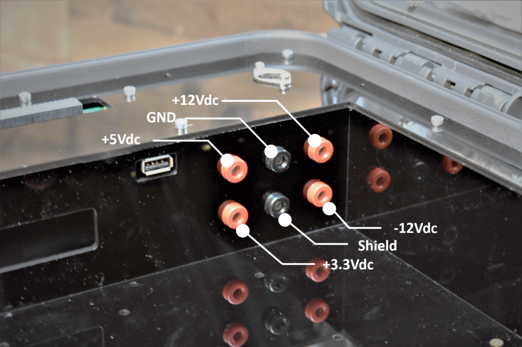
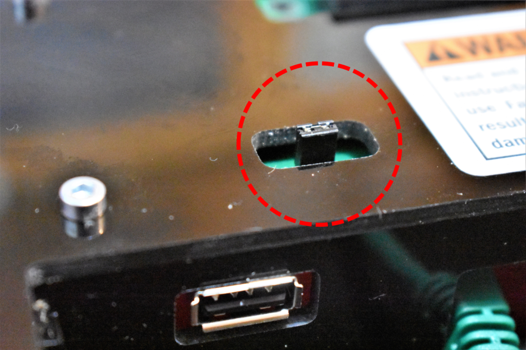
There are four DC voltage rails that the FuelCan provides: +12V, -12V, +5V, and +3.3V. There are also connection points to Ground and Shield. The +12V, -12V, and +3.3V rails are each distributed to one of the red female banana jacks and the 4×26-pin connector. The +5V rail is distributed to one of the red female banana jacks, 4×26-pin connector, and both USB1 and USB2 connectors. On the USB1 receptacle, there is a shunt connector. If it is inserted, +5V will be provided to the USB receptacle. If it is not inserted, then the USB1 receptacle will not provide power.
The Ground is distributed to one of the black female banana jacks and the 4×26-pin connector. The Shield is only distributed to one of the black female banana jacks. The image below shows which banana jack each rail is mapped to.
By distributing the voltage rails to the 4×26-pin connector, each Canister is able to access them, if needed. Please be careful when connecting pins and make sure to consult the connector pinout in section 8. The banana jacks allow you to gain access to each rail via the provided banana jack to test lead clip cables. For example, if you are prototyping a circuit on a solderless breadboard, you have convenient access to power and ground.
Each voltage rail has its own maximum current rating that must not be exceeded. If it is exceeded, then you risk damaging the AC-DC power adapter or any of the components that are connected at the time of overcurrent. The AC-DC power adapter does provide overcurrent protection. However, it is not instantaneous, meaning it takes some time (milliseconds) to shutdown.
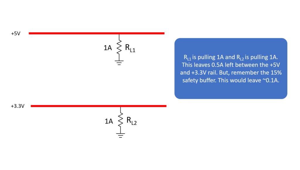
The +12V rail can source up to 1.0A, the -12V rail can source up to 0.3A, and the +5V and +3.3V rails can source a combined amperage of 2.5A. This means that if you have a load powered from the +5V rail and it’s pulling 1A, you have 1.5A left for loads on both the +5V rail and +3.3V rail. Another example is shown below. We recommend that you have a 15% safety buffer from the maximum current rating. For example, 15% of 2.5A is 0.375A, so try to stay under ~2.1A. This is because of current transients that could happen when the circuits are energized. By having this safety buffer, you lower the risk of overcurrent.
To power the FuelCan, plug the cable with the 5-pin male DIN connector into the 5-pin female DIN connector on the FuelCan. These two connectors are keyed, so it only goes in one way. This prevents the connector from being plugged in wrong and possibly damaging components due to voltage mismatch. On the 5-pin male DIN connector it is marked with “TOP,” as shown below. This should be facing towards the Top Subassembly when plugged in.

Once the 5-pin male DIN connector is seated, we can go ahead and plug the AC power cord in. Plug the female side into the AC-DC power adapter, then plug the male side into a 110VAC outlet. You should see an LED light up on the power adapter signifying that power is good. The FuelCan is now powered up.
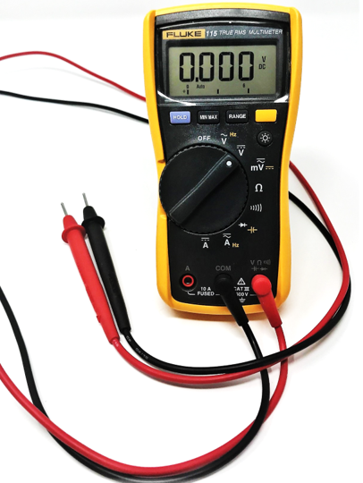
If you want, you can check that each voltage rail is working with a voltmeter. Set the voltmeter to measure DC voltage (image below) and place the black probe into the Ground banana jack. Next, take the red probe and insert it into the +12V, -12V, +5V, and +3.3V banana jacks. The readings won’t be exact. For example, the voltage on my +12V rail reads +12.187V. This is perfectly fine. You will almost never get a reading that is exactly +12.000V or +5.000V as this precision would likely cause the cost of electronics to soar.
Mounting Raspberry Pi 3 Model B/B+
We mentioned that there were eight #4-40 threaded inserts preinstalled in the prototyping area. Four are used to mount a Raspberry Pi 3 Model B/B+ (RPi3) and the other set of four are used to mount an Arduino Uno Rev3. First, we’ll show you how to mount a Raspberry Pi 3 Model B/B+. Both the Raspberry Pi 3 Model B and the Raspberry Pi 3 Model B+ have the same mounting-hole footprint so it doesn’t matter which one you have.
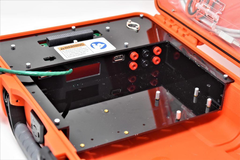
Before screwing in the RPi3, we need to screw in the four #4-40 x 1/4″ male/female hex standoffs. You do not need to torque these standoffs on – just hand tighten them. An image with the hex standoffs installed is below.
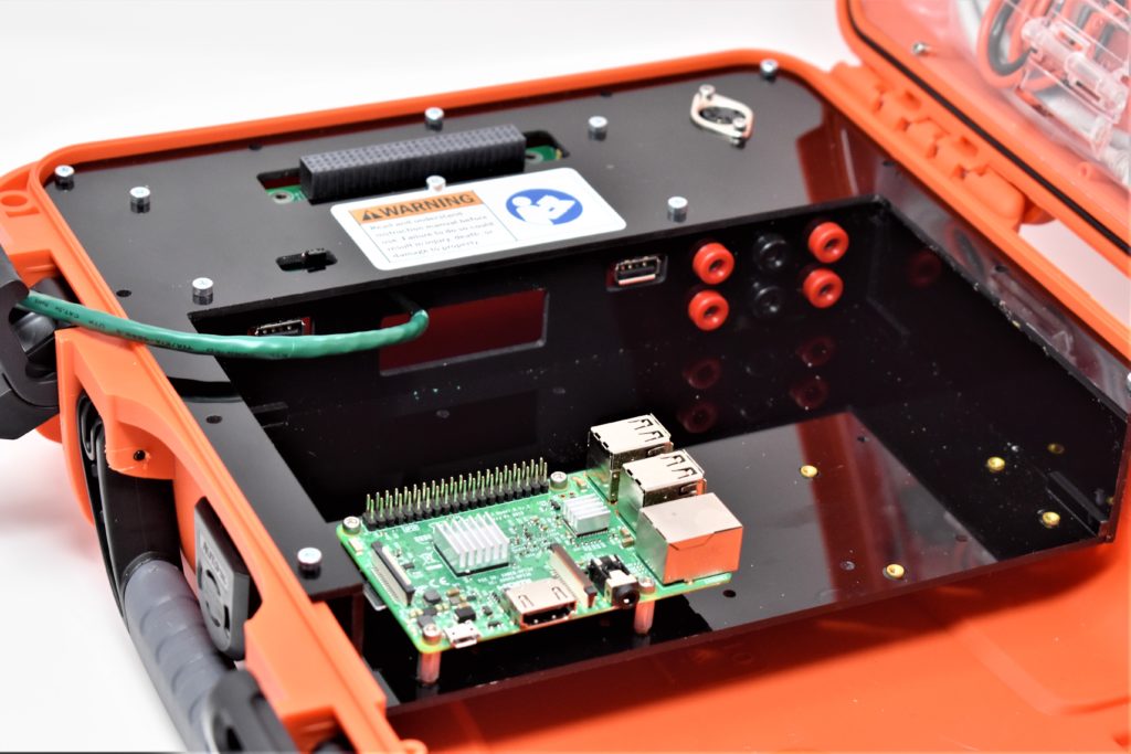
Now we’re ready to mount the RPi3. Orient the board so that the Ethernet and USB receptacles face towards the middle of the FuelCan, and place the board on top of the hex standoffs. Line up the holes and screw in the first #4-40 x 1/4″ socket head cap screw. You’ll need a 3/32″ Allen key or ball-end hex driver to screw them in. Do not tighten the screws all the way until you get each screw in their respective hex standoff. Once all of them are in, go ahead and tighten them one-by-one. An image of the RPi3 mounted is below.
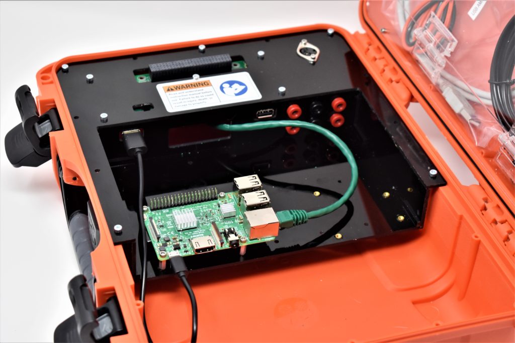
Next, we can plug the 6″ Ethernet cable into the RJ45 jack on the RPi3. If you purchased the optional 1′ Type A to Micro USB cable, plug the Type A side into USB1 (make sure the shunt connector is inserted) and Micro side into the RPi3 to power the board. An image showing the cables plugged in is shown below. Plug in a keyboard, mouse, and an HDMI monitor and you’re ready to start prototyping!
Mounting the Arduino Uno Rev3
We’ll take a similar approach that we did to mount the RPi3 to mount the Arduino Uno Rev3 (Uno). If you followed the steps to mount the RPi3, remove the board and hex standoffs, and screw the hex standoffs into the four threaded inserts for the Uno. The image below shows the placement of the hex standoffs.
Place the Uno on top of the hex standoffs with the Type B USB receptacle pointing towards the middle of the FuelCan. Line up the holes and screw in a #4-40 x 1/4″ socket head cap screw with a 3/32″ Allen key or ball-end hex driver. Do not tighten until you get the rest of the screws in. Once all of the screws are in, lightly tighten each screw. An image showing the Uno mounted in the prototyping area is shown below.

If you purchased the optional 1′ Type A to Type B USB cable, plug the Type B side into the Uno and plug the Type A side into USB1. If you plug it into USB2, you will not be able to program the Uno. An image of the USB cable plugged in is below.
To program the Uno, you have to plug in the 6′ Type A to Type A USB cable – one side plugs into the external USB connector and the other side plugs into a USB port on your computer. To see which external connector is USB, please see section 10.
Canister Installation
Before we dive in, please be careful when handling the Canisters. The pins can become bent if the Canister is not installed properly. We want to make sure that the Canisters last just as long as the FuelCan. If you have more than one Canister, please see section 8 about mating Canisters to create a stack. The Canisters should be stacked first before inserting into the 4×26-pin connector on the FuelCan.
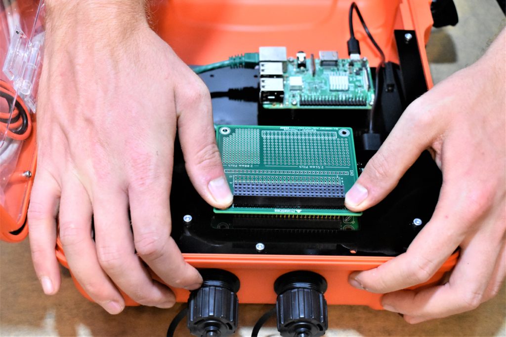
We recommend that you unplug the power adapter from the AC outlet when you plug in the Canister(s). This will reduce the risk of short circuits or damage caused from pin misalignment. If you only have one Canister, line up the male pins of the Canister with the female header on the FuelCan. Make sure that all pins are properly seated before pressing the Canister all the way in. Place your thumbs on the side of the 4×26-pin connector, as shown in the image below, and apply a light downward force to fully insert the Canister. Once it is fully seated, plug the power adapter back in to power up the FuelCan.
Canister Removal
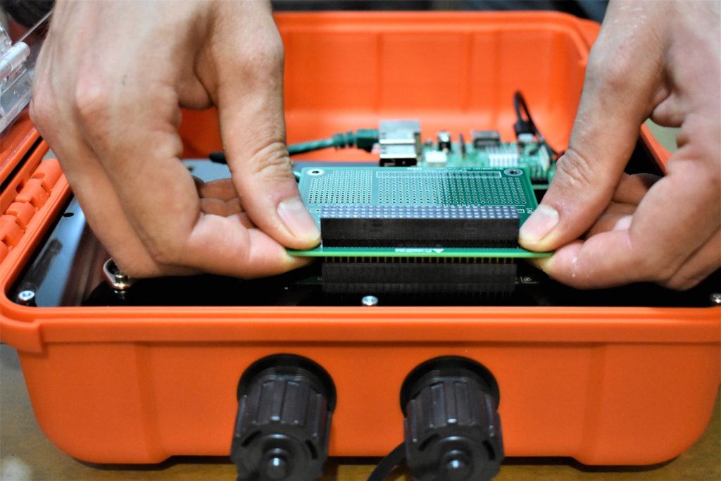
Power down the FuelCan first, before removing the Canister(s). Wait 10 seconds for the capacitors to discharge. To remove the Canister, place your index finger and thumb as oriented in the image below. To overcome the static friction, gently rock the Canister from side to side. Once it starts moving, lift the Canister straight up and out of the female 4×26-pin connector. If you do not lift straight up, you risk bending the pins.

Canister Stack
If you have mulitple Canisters, we highly recommend that you stack them first before inserting the stack into the 4×26-pin connector on the FuelCan. This will prevent an excessive force being exerted onto the Bottom Subassembly.
To stack the Canisters, hold one Canister in one hand, and the other in your other hand. Next, line up the A1 pins on both Canisters and make sure that all of the pins line up before pressing them together. Once you confirm that all the pins are properly seated, apply pressure around the 4×26-pin connector to fully mate them. You should hear a snap when they mate.
4x26-Pin Connector Pinout
The connector pinout is fixed so you cannot change the pinout. For example, the voltage rails and ground are mapped to certain pins on the 4×26-pin connector which cannot be changed. Make sure to consult the pinout frequently to determine the function of each pin. The pinout is in the image below and it is also in the FuelCan User Guide.
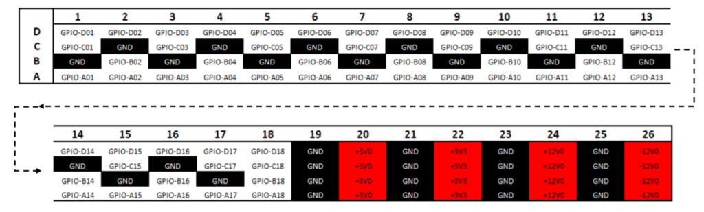
On the Main Interface PCB you’ll notice that the 4×26-pin connector has letters A, B, C, and D, and there is the number 1 in the bottom left corner. This is outlined in the image below. These help identify the designator of each pin. For example, the pin in the bottom left would be A1 (GPIO-A01) and the pin in the top right would be D26 (-12V0).

To give you an example, say you need to power a sensor that you mounted to the Modulus Canister. This sensor requires +5V, Ground, and a Signal wire. Go to the pinout to determine what pins you can use. You can use any of the +5V pins which are A20, B20, C20, and D20. The Ground pins are in black (doesn’t matter which one you choose) in the pinout diagram, and you can use any of the pins marked as GPIO (again, doesn’t matter which one you choose). I’ll use pin A20 for +5V, pin A19 for Ground, and pin A18 for Signal. You do want to try to cluster the wires around each other for each sensor. This will help you stay organized and keep your wiring looking clean.
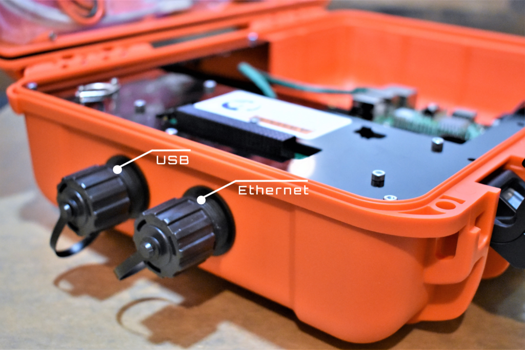
External Connectors
There are two external connectors attached to the side of the Nanuk case. These are IP67-rated which means that they’re waterproof. However, when you screw off the cap and plug in the cable, they are no longer waterproof. One connector is for Type A USB and the other is for Ethernet which is outlined in the image below. These will only work if you have a development board that supports these interfaces. The FuelCan itself does not communicate with the host.