Last updated August 2019
Introduction
Welcome to the world of embedded computing! The Raspberry Pi 4 is the perfect board to get started with since it is extremely user-friendly and there are tons of free projects available that you can do. This is a single-board computer meaning that it can do just about anything that a laptop or desktop can do. One advantage that it has over a laptop or desktop is that you have access to a 40-pin GPIO (General Purpose Input/Ouput) header which allows you to connect sensors or modules!
In this quick-start guide, we discuss the hardware available on the Raspberry Pi 4, how to load an operating system onto it and power it up, show you some basic commands to use in the terminal, and write some Python code to blink an LED that is connected to a GPIO pin.
Disclaimer
ProteShea, LLC is a participant in the Amazon Services LLC Associates Program, an affiliate advertising program designed to provide a means for sites to earn advertising fees by advertising and linking to Amazon.com
Some links may be affiliate links, in which ProteShea, LLC earns a commission if you use that affiliate link. Please note that this is at no additional cost to you and helps us in creating more content.
Here’s what you’ll need to get started:
- Raspberry Pi 4 Model B
- FuelCan (optional)
- Modulus Canister (optional)
- Modulus Kit
- Solderless breadboard
- USB-SD adapter (optional)
- DVI-to-HDMI adapter (optional)
- 12″ F/M jumpers
- 30 AWG wire
- 30 AWG wire wrap tool
- Soldering iron
- Solder
Hardware
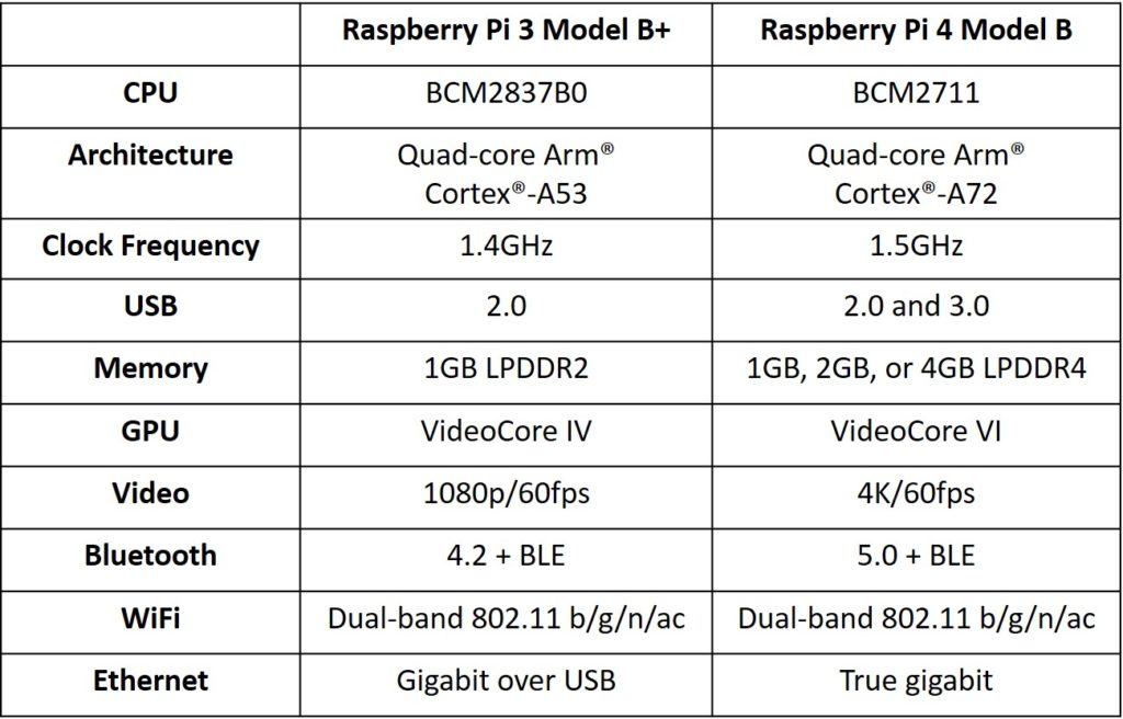
The Raspberry Pi 4 Model B boasts more speed, performance, memory, and connectivity over the Raspberry Pi 3 Model B+. The table below shows a side-by-side comparison between the Raspberry Pi 3 Model B+ and Raspberry Pi 4 Model B.
There are tons of features packed into the small device as shown in the below image. The Broadcom BCM2711 CPU (Central Processing Unit) is a 64-bit architecture with a quad-core Arm® Cortex®-A72 and can be clocked at 1.5GHz (there are benchmarks that show it can be overclocked up to 2GHz). If you decide to overclock it, make sure to add a cooling fan or the Pi will thermal throttle (decrease the frequency) due to overheating.
The board has three different options for SDRAM memory: 1, 2, or 4 GB LPDDR4-2400. It has true gigabit ethernet and can be connected via WiFi on 2.4GHz or 5.0GHz. You can also connect to it via Bluetooth.
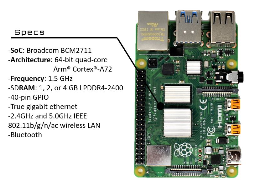
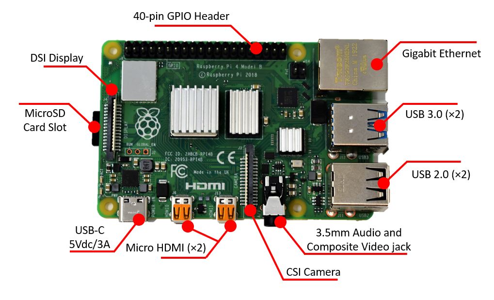
There are many different connectors which include the 40-pin GPIO header, USB 2.0 and USB 3.0 ports, micro HDMI, microSD card slot, DSI display, CSI camera, and a 3.5mm audio and composite video jack. An image is shown below that points out each connector.
General Purpose Input/Output (GPIO)
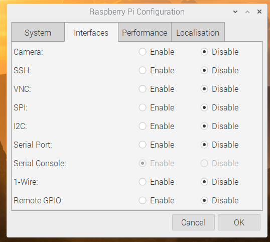
The GPIO is one of the best things about not only the Raspberry Pi 4, but the entire Raspberry Pi family. It gives you access to the pins of the SoC (System on Chip), the brain of the Pi. The pins can be configured as an input or output, and some of the pins can be used for communication protocols such as I2C, UART, and SPI. To use these protocols, you have to use the Raspberry Pi Configuration to set the Interfaces, which is shown in the image below.
The pins have an operating voltage of 3V3 (the operating voltage for the GPIO on an Arduino Uno is 5V) and a max current draw of 16mA. All of the pins are digital, meaning that they only have two states, 0 and 1. There are no analog input or output pins since there is not an analog-to-digital (ADC) or digital-to-analog (DAC) converter.
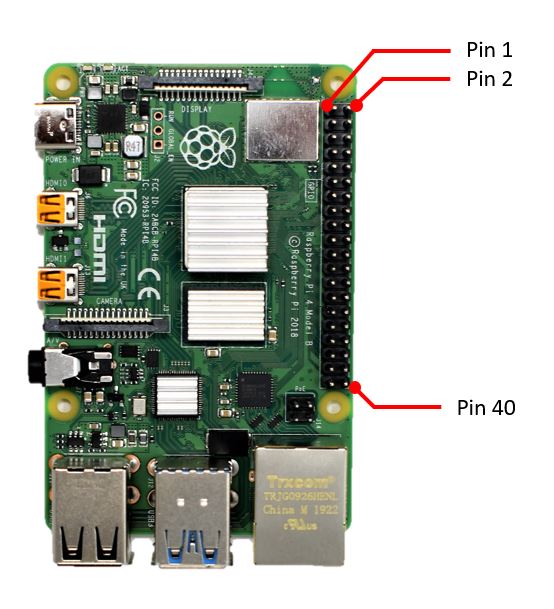
The pin numbering starts in the top-left corner closest to the microSD card slot, as shown in the image below. With the orientation shown below, the odd pin numbers are on the left side and the even pin numbers are on the right side of the header. This is often referred to as the physical location of the pin. Be aware that the pin number does not correspond to the GPIO number. For example, Pin 3 is not GPIO 3, it is GPIO 2.
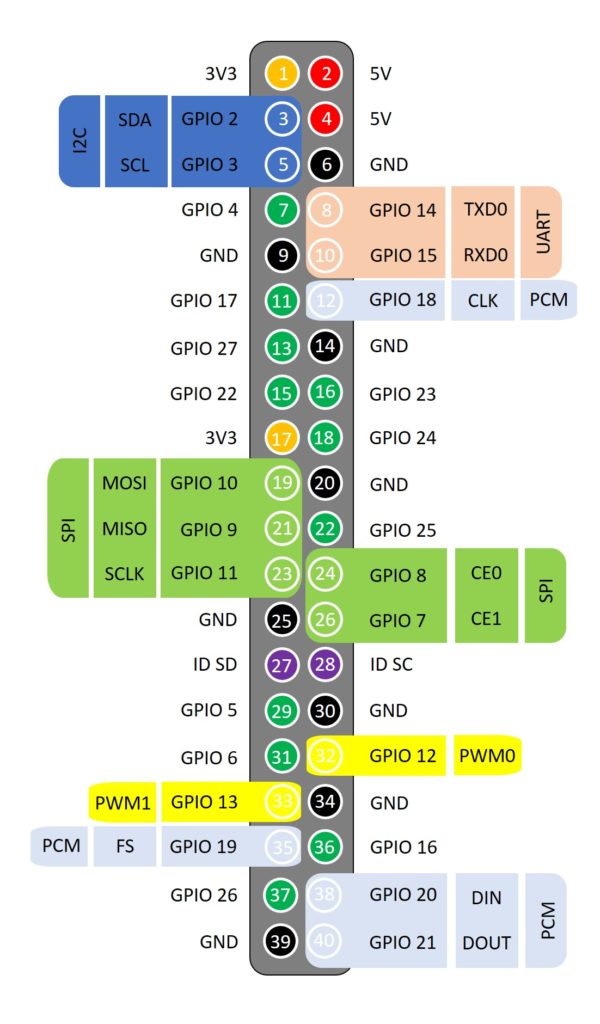
The pinout for the 40-pin header is shown in the image below.
How to Install an Operating System
When you receive your Raspberry Pi, it doesn’t work right out of the box. To get it to work, we have to install an operating system (OS). There are numerous operating systems that you can choose from, but the most popular one is Raspbian which we’ll be installing. Installing Raspbian can be done with one of two methods: 1) using NOOBS (New Out Of the Box Software) or 2) using Etcher or Win32DiskImager to flash Raspbian right to the microSD card.
We’ll only cover how to perform the first method, using NOOBS, since it’s the easiest and you do not need to install any extra software to flash the OS onto the microSD card. To begin, download the NOOBS ZIP file by clicking the button below. The file is about 2.1GB so it will take some time to complete the download.
While we’re waiting for the ZIP file to download, we’re going to format the microSD card. It is recommended that you use an 8GB or higher card – we’ll be using a 32GB microSD card. Insert the microSD card into the SD card adapter and plug it into your laptop or desktop. If your computer does not have a SD card slot, you can use an USB-SD adapter.
MacOS and Linux have built-in formatting tools. If you’re using Windows, it depends on which version you have installed. You can do a quick check by opening up Windows File Explorer and right-clicking on the microSD card that was just inserted. If you have a built-in formatter, you should see Format…. Once you click that, you’ll see a window similar to the image below. If you do not have this, you can download SD Memory Card Formatter.
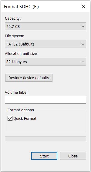
Make sure the File system is set to FAT32. You can give your SD card a name under Volume label such as RPi4. Then, click the Start button to begin formatting the card. It should take no time at all.
NOTE: clicking the check box for Quick Format will erase the entire SD card. Make sure you save all your files before proceeding.
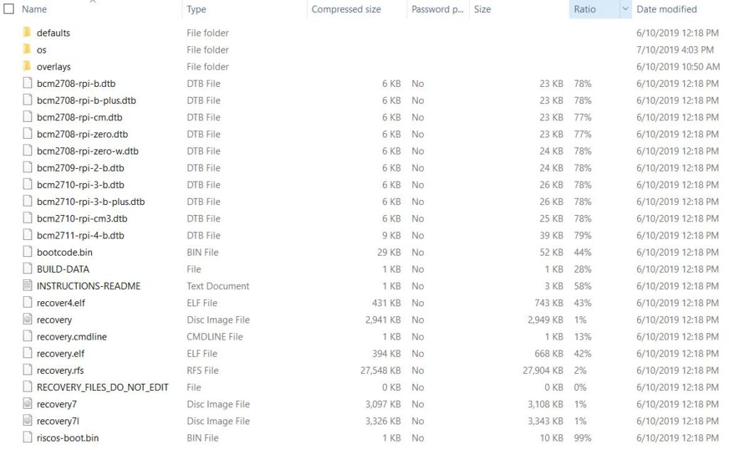
Navigate to the folder where the NOOBS ZIP file was downloaded to and extract the files. Copy all the files to the microSD card that you just formatted. Your microSD card should contain the files that are shown in the image below.
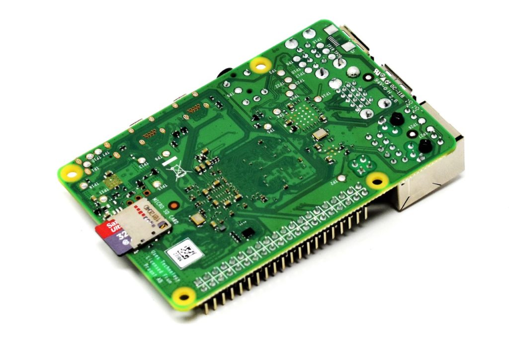
Eject the card from your laptop or desktop and insert the microSD card into the slot on the Raspberry Pi 4, as shown in the image below. It is located underneath the board.
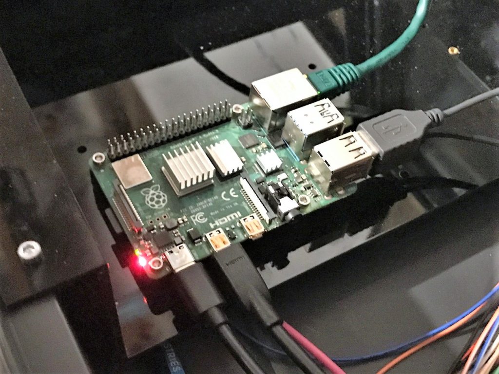
Connect Mouse, Keyboard, Display, and Power Supply
Before powering on the board, we need to connect a USB mouse and keyboard. You can plug them into any USB port, but remember that there are two USB 2.0 and two USB 3.0 ports. You don’t need a USB 3.0 port for a mouse or keyboard, but feel free to use it. The USB 3.0 ports should be used for high data rate devices like an external solid state drive.
Next, use a HDMI to micro HDMI cable to connect a HDMI monitor. The Raspberry Pi can support a monitor up to 4k resolution. If your monitor does not have a HDMI port, but it has a DVI port, you could use a DVI-to-HDMI adapter.
Now that we have all of our devices connected, we can power up the Raspberry Pi. Make sure that you use a recommended USB-C power supply which has a 5Vdc output and can source at least 3A. The standard power supply that comes with the FuelCan can only source 2.5A so you’ll have to upgrade to the 50W power supply, or purchase a recommended USB-C power supply for the Pi. One thing to note is that the board does not have a power switch (similar to the previous models), so as soon as you plug in the USB-C supply, it will power up.
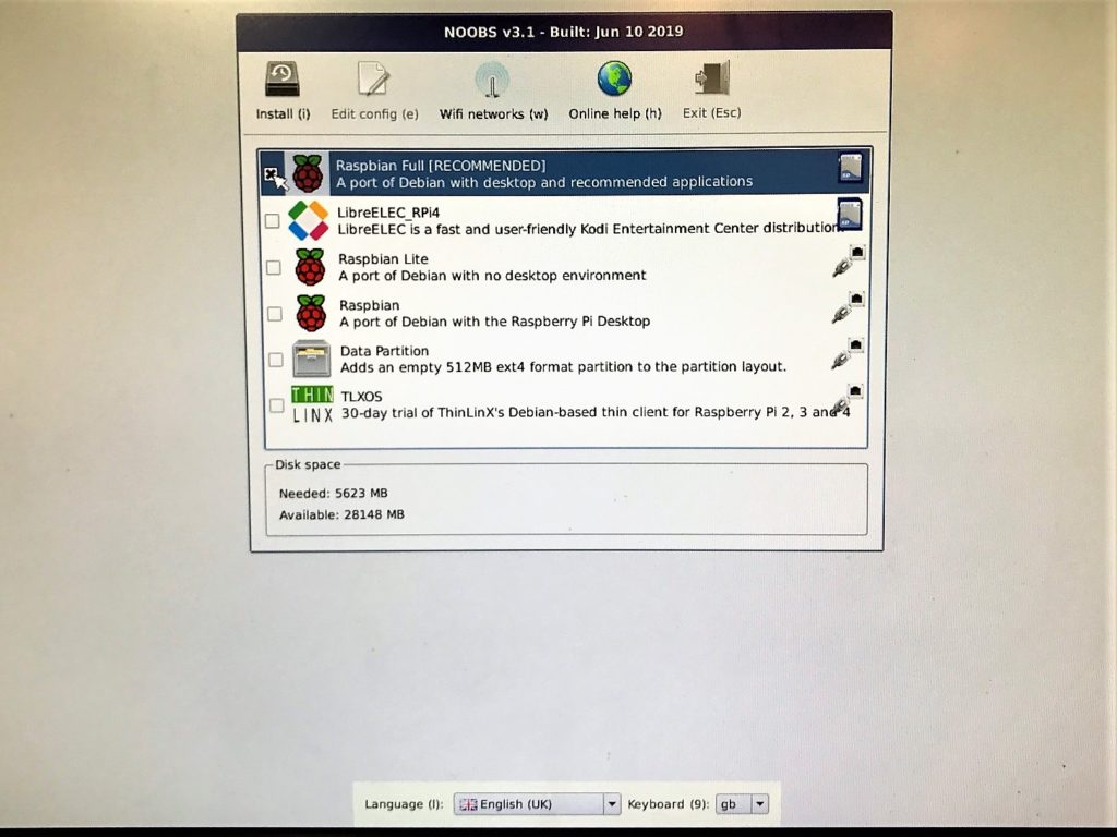
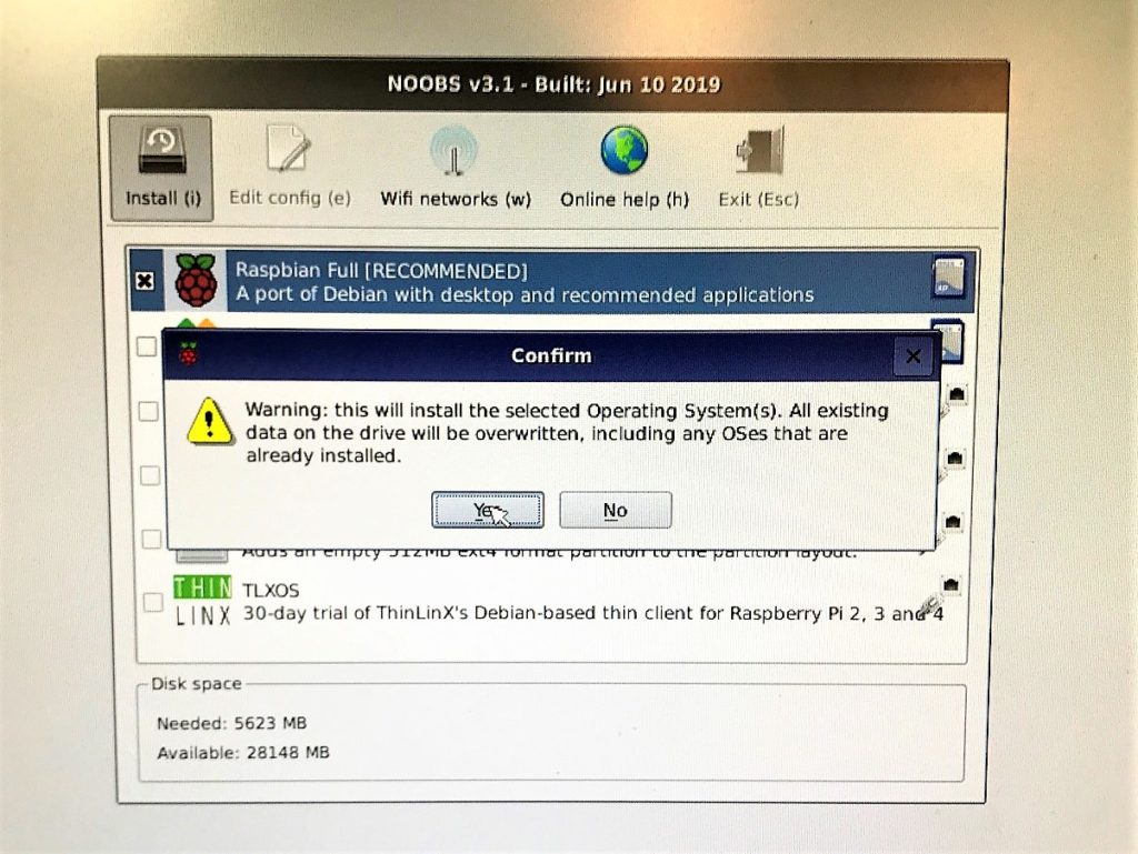
Once it powers up, you’ll be asked to choose which operating system you want to install. Raspbian Full is recommended since it installs the desktop environment and applications. If you do not need the desktop environment or the extra applications, you can opt for Raspbian Lite. Raspbian Lite requires less disk space at 1588 MB. Don’t forget to choose your language and keyboard layout at the bottom of the screen!
After you make your selection, click Install and select Yes to confirm. The software will start to download onto the microSD card. It will take around 10 minutes to complete.
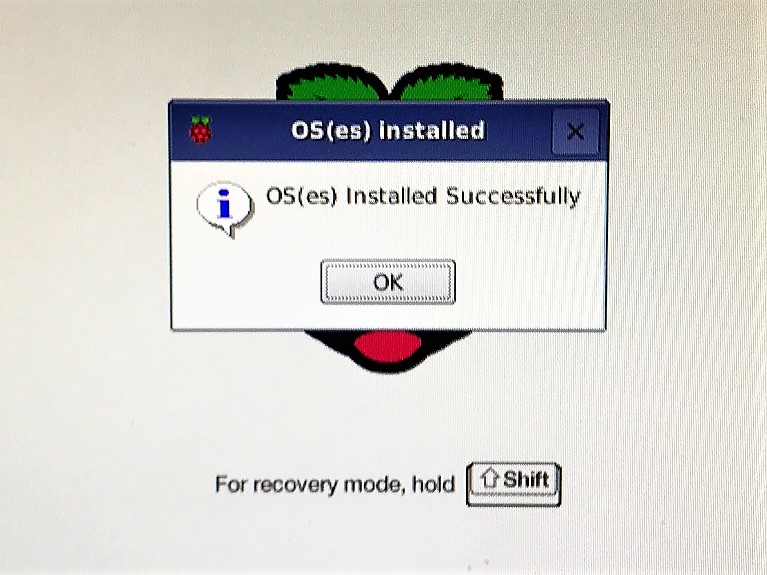
If the operating system was successful, you should receive a message saying that it was installed successfully. Click OK and the board will boot the operating system.
Once the OS has been loaded, you’ll be asked to set your country, language, and time zone. After that, choose a new password other than the default. If you’re using WiFi, choose your network or skip it if you are already connected to the ethernet with a hard-wire connection.
Terminal
One of the great things about Raspbian (or any Linux distribution for that matter) is the terminal (also called command line). Within the terminal, you can do just about everything – check your network settings, set a static IP address, write and build code, navigate the file structure, launch a web browser, etc. You should not be afraid of using the terminal because it can be extremely powerful and efficient.
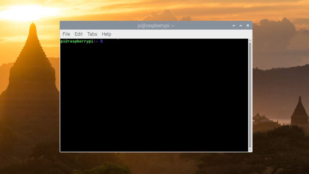
To open up a terminal you can click the Terminal icon in the top-left corner or press Ctrl + Alt + t for a shortcut. You should see the terminal window pop up, as shown in the image below.
There are five easy commands that you should know right away:
- cd – used to change the directory
- ls – lists the contents within a folder
- pwd – lists your current working directory
- clear – clears the previously executed commands
- mkdir newdir – creates a new directory where “newdir” is the name of the directory
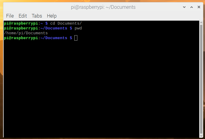
Let’s try each command above. Let’s say we want to navigate to the Documents/ folder. To do this type the following command:
cd Documents/
You should now be in the Documents folder which is indicated by the blue text ~/Documents. You can further verify this by typing the command pwd which prints your working directory.
Now that we know that we’re in the Documents folder, we can now use the command ls to see what files are contained in this directory. Since we just installed a fresh copy of Raspbian and we haven’t saved any files yet, there should be nothing inside of the folder. Let’s back out to our home directory (/home/pi) by typing cd and then type ls to list its contents. You should see the following folders (folders are blue) as shown in the image below.
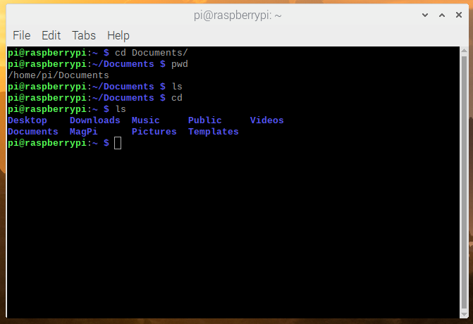
Okay, we know how to use cd, ls, and pwd. Let’s clear our previously executed commands in the terminal by typing clear. This gives us a fresh new window.
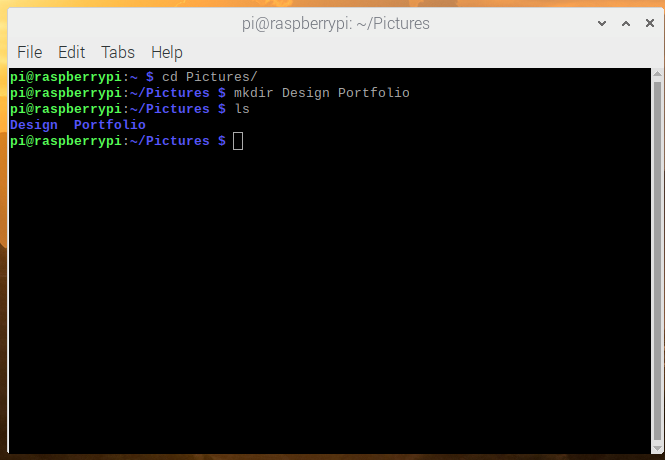
Our next command is mkdir which is used to create a new directory. As an example, navigate to the Pictures/ directory and create a new folder called “Design Portfolio” to hold pictures of all your projects you’ve worked on. Then, type ls to verify that your new folder was created.
cd Pictures/
mkdir Design
ls
Blink an LED
Unlike the Arduino Uno Rev3, the Raspberry Pi 4 does not have an on-board LED, so we have to create our own circuit using the Modulus Canister or a solderless breadboard. Getting an LED to blink on any new piece of hardware is a fundamental step because it means that you can:
- write and build code that runs
- configure a GPIO pin as an output
- set the GPIO pin HIGH and LOW
- create a delay between toggling the output pin
To limit the current passing through each LED, we’ll be using a 470 ohm, 9-resistor array. If you do not place a resistor in series with the LED to limit the current, you could damage the LED or output pin on the Pi.
There are two important numbers to look for in the LED’s datasheet. The first one is the forward voltage which is the voltage drop across the LED. This is usually given as a maximum rating, so you want to make sure to keep the voltage at or below the forward operating voltage. The second is the forward current which is the maximum current that should be sourced to the LED. For example, the forward voltage and current for each LED in the bar graph is 2.6V and 25mA, respectively. The circuit for one LED is shown below.
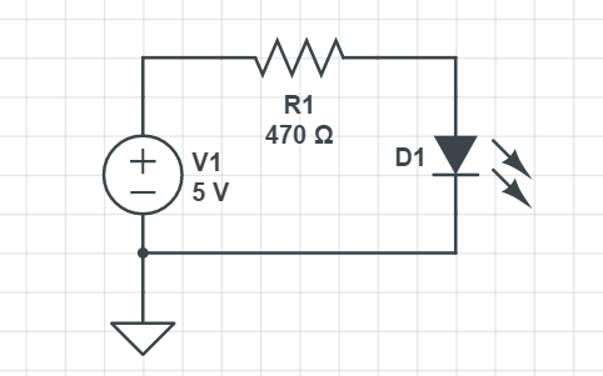
The 470 ohm resistor is a little high when connecting to a 5V source. The current through the LED will be around 5mA, but the LED is still bright enough. We did this because the FuelCan does provide +12V, so if you wanted to use that rail for the LEDs, you’d still be under the forward current rating.
You can place the resistor before (as shown above) or after the LED. It will still limit the amount of current sourced through the LED.
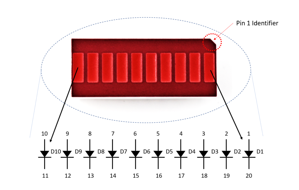
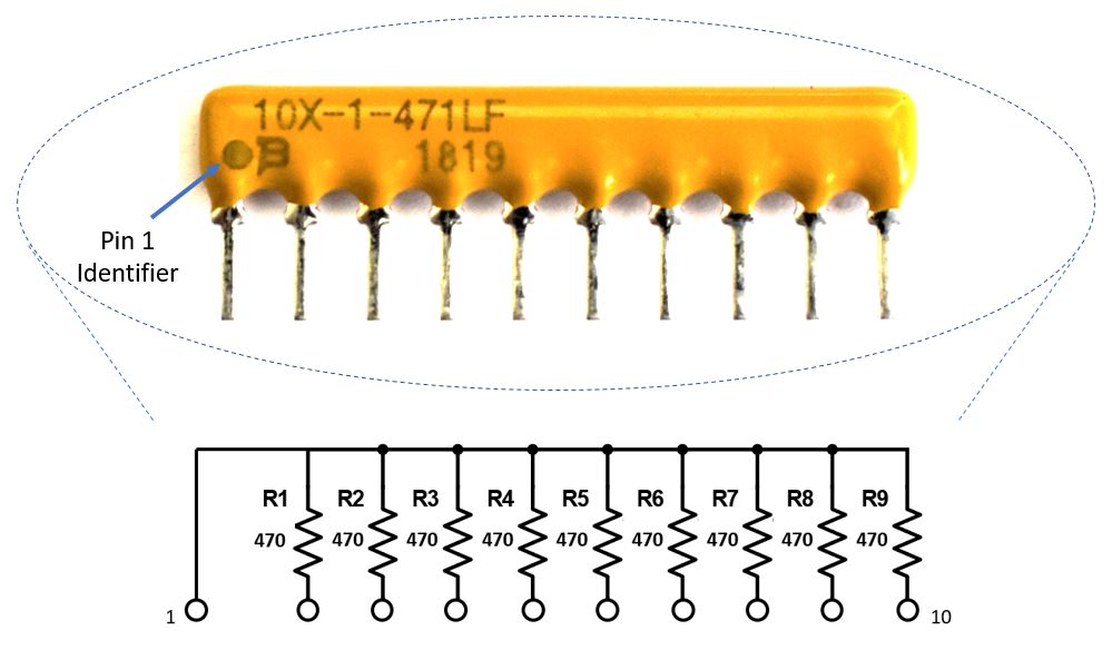
470Ω Resistor Array
The resistor array is made up of a number of bussed resistors, which means that one lead of each resistor shares a common node with the other resistors in the array. These are beneficial for adding a series resistor to multiple, identical components such as the LED bar graph or a switch array. They also help with keeping your wiring clean and compact.
The internal circuitry of the 470Ω resistor array is shown in the image below. When you look at the resistor array, pin 1 is identifiable with the dot. This can be connected to power or ground, but make sure to consult the datasheet for the max voltage rating if you are connecting it to power.
Circuit Wiring
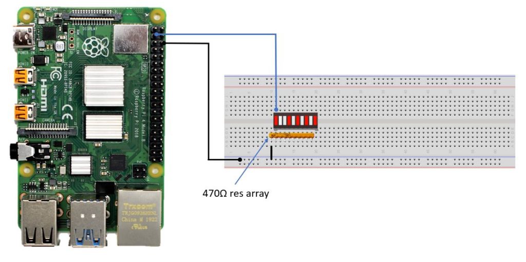
I’m using a breadboard instead of Modulus for this example. First, let’s place the LED bar graph onto the breadboard by inserting it so that the body is over the valley of the breadboard. You do not want the pins to short each other by being connected to the same node. Next, place the 470Ω resistor array on the cathode side of the LED and tie pin 1 of the array to GND. Make sure that pin 1 of the resistor array is not connected to any of the cathodes of the LED bar graph.
Next, use a F/M jumper to wire one anode of the LED bar graph to GPIO 2 which is on pin 3 of the Pi. This pin will get set as an output to drive the LED. A schematic is shown below.
Software
Our LED circuit is complete, so let’s move on to the software. We will be writing the code in Python and leveraging a very useful GPIO library called RPi.GPIO. To write the code, we’ll be using Thonny which comes preinstalled with Raspbian. Simply click the main menu button in the top-left corner, choose Programming, then click Thonny Python IDE.
The first thing we need to do is import the library functions we want to use which are RPi.GPIO and time. The RPi.GPIO library allows us to specify a GPIO pin as an output and toggle the output HIGH and LOW. The time library is used for a delay – in this example, we set a delay of 0.5 seconds or 500 msec.
We want this code to run forever until a user cancels it, so we use while True: and place the code inside of this function. The code is simple – we set GPIO 2 HIGH to turn the LED on, wait 0.5 seconds, set GPIO 2 LOW to turn the LED off, and then wait another 0.5 seconds.
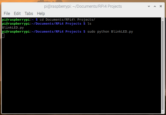
To run the code, save and click the Run button. You could also run the code from the Terminal. Open a terminal with Ctrl + Alt + t, and navigate to the directory where you saved the code. Type sudo python <nameofcode>.py. You should see the LED blinking. To stop the code from running, click the Stop button in Thonny, or press Ctrl + c in the terminal.