Interface Ultrasonic Sensor with Arduino Uno
Last updated May 2019
Introduction
Welcome to ProteShea – in this project, we’ll be replacing the PIR sensor to interface an ultrasonic sensor with the Arduino Uno. The PIR sensor was used to detect movement while the ultrasonic sensor is used to measure distance to an object that is within the sensor’s field of view. The ultrasonic sensor is useful in obstacle avoidance and other systems that require distance as a variable.
Disclaimer
ProteShea, LLC is a participant in the Amazon Services LLC Associates Program, an affiliate advertising program designed to provide a means for sites to earn advertising fees by advertising and linking to Amazon.com
Some links may be affiliate links, in which ProteShea, LLC earns a commission if you use that affiliate link. Please note that this is at no additional cost to you and helps us in creating more content.
Here’s what you’ll need to get started:
16x2 Character LCD
Please see Project 9 on how to interface the 16×2 LCD in 4-bit mode. You should have pins 4, 6, and 11-14 of the LCD connected to Uno pins 2, 3, and 4-7, respectively. The LCD is mounted to the Modulus Canister via the 16-pin, right-angle female header soldered to the 1-to-1 link, as shown in the image below.
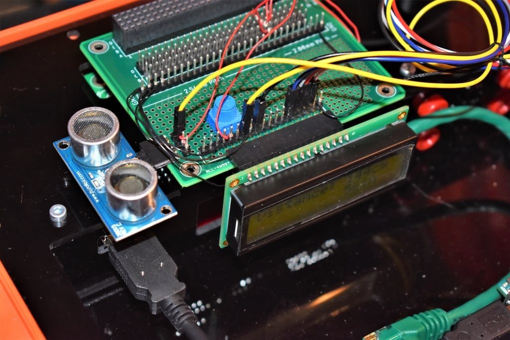
Parallax Ultrasonic Sensor
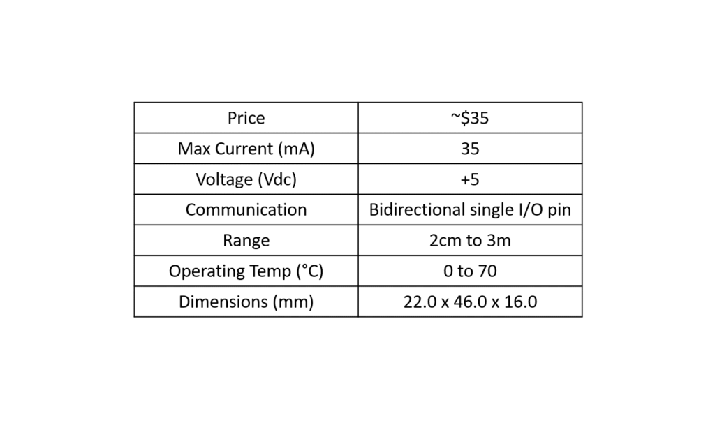
The ultrasonic sensor from Parallax consists of 3 pins: GND, 5V, and SIG. The SIG pin is used as both an input and an output. It is an input when the Uno sends a HIGH pulse to trigger the sensor to take a measurement, and it is an output when the sensor sends a HIGH pulse where the length of the pulse is dependent on the time it takes for the transmitted sound wave to return. It can measure the distance to an object that is within 2 centimeters to 3 meters. A table of specifications is shown below.
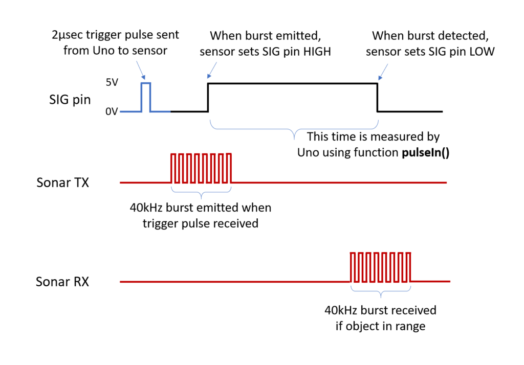
The sensor works by emitting a burst of ultrasonic sound waves (not detectable by human hearing) at 40kHz and measuring the time it takes for the waves to return back (if there is a detectable object). To initiate a burst, the host (Uno) must send a 2 microsecond HIGH trigger pulse. The sensor then sends a burst of eight pulses through the air (chirp), sets the SIG pin HIGH, and waits for the waves to travel back (echo). When the echo is detected, the sensor sets the SIG pin LOW. The width of this HIGH pulse on the SIG pin corresponds to twice the distance to the target, since it’s measuring the time it takes the waves to travel to and from the object.
A timing diagram of the sensor is shown below. The difference in color of the SIG pin’s waveform signifies which device is controlling the pin. For example, the Uno controls the pin to send a trigger pulse (blue) and then the sensor controls the pin to send the HIGH pulse (black).
Since the received pulse from the sensor is in time, we have to perform some calculations to convert the time into distance. The speed of sound travels at 1130 feet per second or 340 meters per second. First, we need to convert the 340m/s into cm/sec by multiplying by 100 which is 34,000cm/sec. Then, convert cm/sec into cm/μsec by dividing by 1E6 which is 0.034cm/μsec. The result using dimensional analysis is shown below.
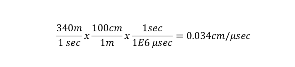
Next, we need to use the distance formula (d = r × t). We know the rate, r, which is 0.034cm/μsec, and we know the time, t, which is acquired from using the pulseIn() function.
For example, let’s say we get a pulse from the sensor that is 100μsec. Using the distance formula, we get d = 0.034cm/μsec × 100μsec = 3.4cm. But, remember, we have to divide by 2 because the returned pulse is the time it takes for the sound wave to travel to and from the object. As a result, the final answer is 3.4cm/2 = 1.7cm
Connecting the Ultrasonic Sensor to Modulus
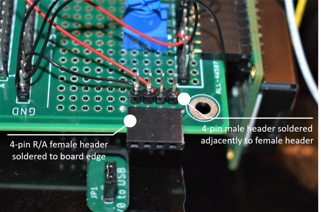
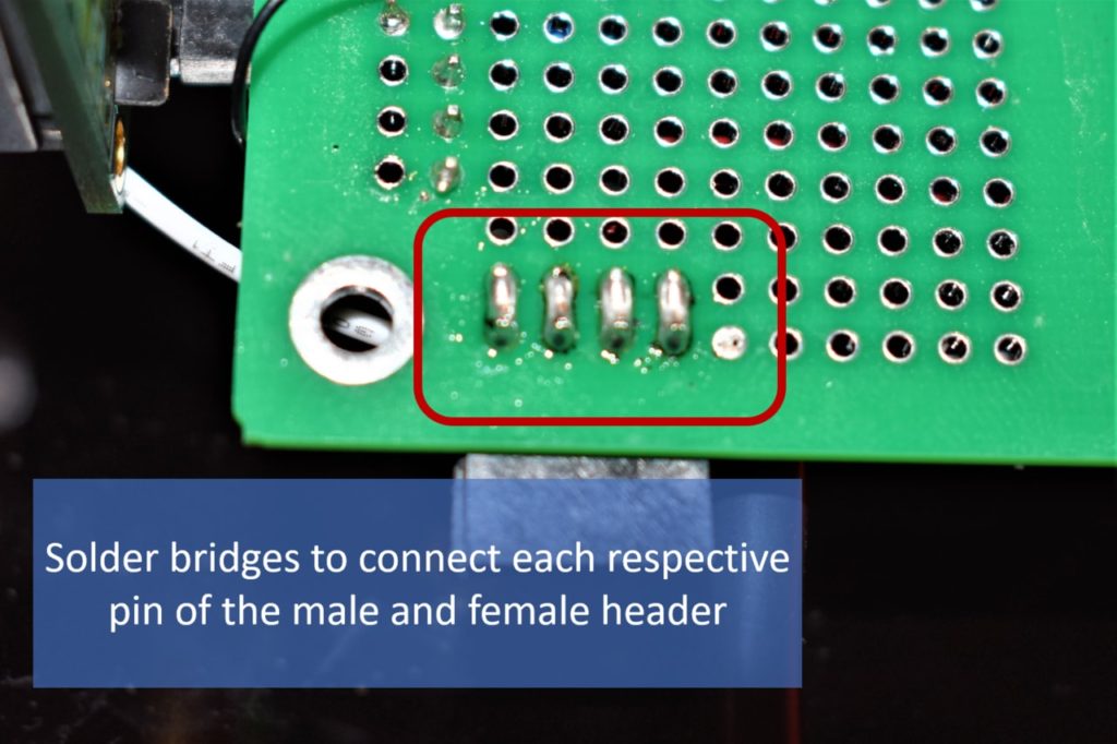
If you completed Project 11, remove the PIR sensor and insert the Ultrasonic sensor. You should have the 4-pin R/A female header soldered to Modulus and there should also be a 4-pin single-row male header soldered adjacently to the R/A female header. This is used so we can wire-wrap 30 AWG wire to the pins. You have to create a solder bridge between each contact to connect the adjacent pins on the female header to the male header. Images of the headers, solder bridge connections, and installed sensor are shown below, respectively.
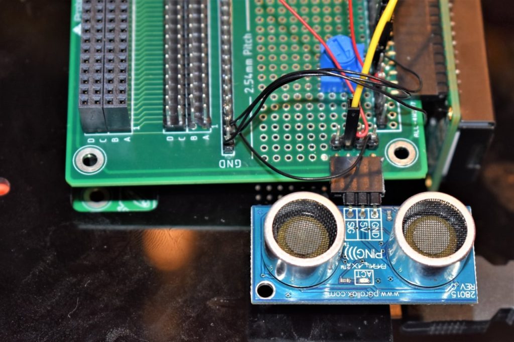
Once the headers are soldered on, plug the Modulus Canister into the 4×26-pin connector on the FuelCan, and insert the ultrasonic sensor as shown above. Starting from the rightmost male header pin, wire-wrap that pin to GND and the second pin from the right to +5Vdc on the 4×26-pin breakout. Next, use a 12″ F/M jumper wire to connect the third pin from the right to pin 8 on the Uno.
Solderless Breadboard
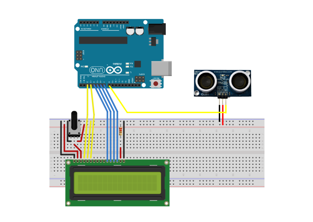
If you are using a solderless breadboard, use the schematic below to make the necessary connections.
FuelCan Wiring
If you haven’t mounted the Uno onto the prototyping area of the FuelCan, go ahead and do that. If you are using a breadboard instead of Modulus, place the breadboard in the bottom storage compartment to limit the length of the jumper wires. You’ll need to supply +5V and GND to the power and ground rails on the breadboard by using the provided banana jack to test-lead clip cables. You will need two male header pins to mount the test-lead clips on the breadboard side. Plug the Type A side of the USB cable into USB1 receptacle and the Type B side into the Uno’s receptacle. Power up the FuelCan with the AC-DC power adapter.
Software
Once the wiring is complete and the FuelCan is powered up, we can now load the sketch onto the Uno. The sketch is below. First, pin 8 is set as an output, so we can send the trigger pulse to the sensor and initiate an ultrasonic burst. Pin 8 is set HIGH for 2 microseconds, and then the pin is set LOW to create the pulse. Next, the pin is set as an input to read the return pulse from the sensor. To measure the duration of the return pulse, we use the function pulseIn() which takes two arguments – the first argument is the pin number that you want to read the pulse on and the second argument is the type of pulse to read (either HIGH or LOW).
Once the pulse width is acquired (returned as time in microseconds), we have to convert the time to a distance measurement. The time is first converted to centimeters and then the calculated measurement in centimeters is converted to inches. The two distance measurements are displayed on the LCD, and pin 8 is then set to an OUTPUT to trigger the next distance measurement.
Further Reading - Using the HC-SR04 Module
Another substitute for the ultrasonic sensor is the HC-SR04 module. Instead of 3-pins, it has 4-pins: VCC, TRIG, ECHO, and GND. Remember how we had to switch the pin mode from output to input for the Parallax sensor? You do not have to do that with the HC-SR04 since there are separate pins, TRIG and ECHO.
You would send a trigger pulse (this one has a minimum of 10μsec) on the TRIG pin, and then receive the HIGH timing pulse on the ECHO pin. The software for the HC-SR04 module is below. The TRIG and ECHO pins are connected to Uno pins 8 and 9, respectively.
About Author
Eric Shea is the founder of ProteShea and is an electrical engineer. He wishes to have a major impact on bridging the gap between engineering theory and real-world applications. He has worked at Kratos Defense, SpaceX, Air Force Research Laboratory, and Polaris Industries. He received a M.S. in electrical engineering from the University of Pittsburgh and a B.S. in electrical engineering from the University of Florida.