Displaying Temperature and Humidity on an LCD
Last updated May 2019
Introduction
Welcome to ProteShea – in this project, we’re going to interface a DHT11 temperature and humidity sensor, and display the data on a 16×2 LCD. If you haven’t read Project 9 for the Arduino Uno Rev3, please read that first because this covers how to interface a 16×2 character LCD in 4-bit mode. We will also swap out the 16×2 LCD for a 20×4 LCD to display the humidity and the temperature in Celsius, Fahrenheit, and Kelvin.
Disclaimer
ProteShea, LLC is a participant in the Amazon Services LLC Associates Program, an affiliate advertising program designed to provide a means for sites to earn advertising fees by advertising and linking to Amazon.com
Some links may be affiliate links, in which ProteShea, LLC earns a commission if you use that affiliate link. Please note that this is at no additional cost to you and helps us in creating more content.
Here’s what you’ll need to get started:
- FuelCan
- Modulus
- Modulus Kit
- DHT11 temperature and humidity sensor
- 16×2 and 20×4 (optional) character LCD
- Arduino Uno Rev3
- 12″ F/M jumpers
- 30 AWG wire
- 30 AWG wire wrap tool
- Soldering iron
- Solder
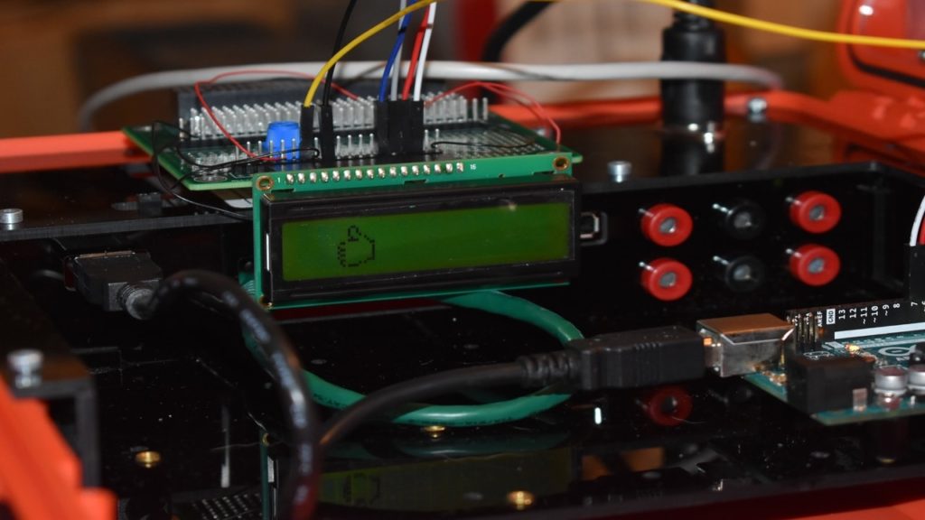
16x2 Character LCD
Please see Project 9 on how to interface the 16×2 LCD in 4-bit mode. You should have pins 4, 6, and 11 – 14 of the LCD connected to Uno pins 2, 3, and 4 – 7, respectively.
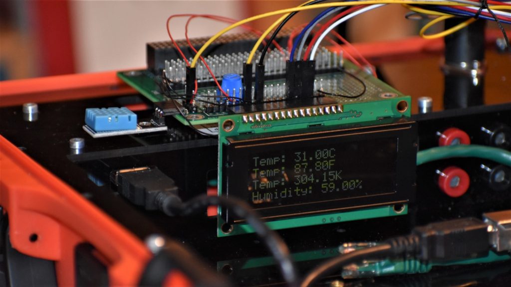
20x4 Character LCD
The 20×4 LCD adds two extra rows and four extra columns per row compared to the 16×2 LCD. Similar to the 16×2, the 20×4 LCD uses the Hitachi controller so the commands and interfaces are the same. It also has the same 16-pin header, allowing you to unplug the 16×2 LCD and plug in the 20×4 without changing any wiring. The only thing we have to change is one line of code, lcd.begin(20, 4), which specifies the columns (first argument) and rows (second argument) of the LCD.
DHT11 Temperature and Humidity Sensor
There are different types of DHT sensors such as the DHT11, DHT21, DHT22, DHT33, and DHT44. They all measure both temperature and humidity, but the difference lies mostly in their accuracy and sampling rate. For example, we show a side-by-side comparison in the table below of the two most popular DHT sensors, DHT11 and DHT22. The DHT22 has a better accuracy and range, but it has a slower sampling rate, it’s bigger in size, and double the cost of the DHT11.

To measure the temperature and humidity, a thermistor and a capacitive humidity sensor are used, respectively. The resistance of a thermistor changes with a change in temperature – as the temperature increases, the resistance decreases. For the humidity sensor, the resistance between the two electrodes changes with a change in humidity. Both of these changes in resistance are measured by the IC on the sensor and sent to the host via a 1-wire interface. Each sample consists of a 40-bit data packet.
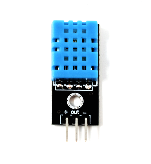
We are using a 3-pin DHT11 sensor as shown in the image below. The pins are “+”, “OUT”, and “-.” The sensor can be supplied with both +5Vdc or +3.3Vdc – we’ll be supplying +5Vdc to it.
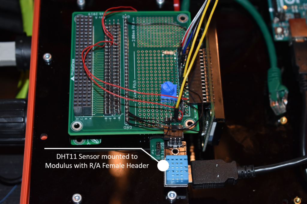
DHT11 Wiring
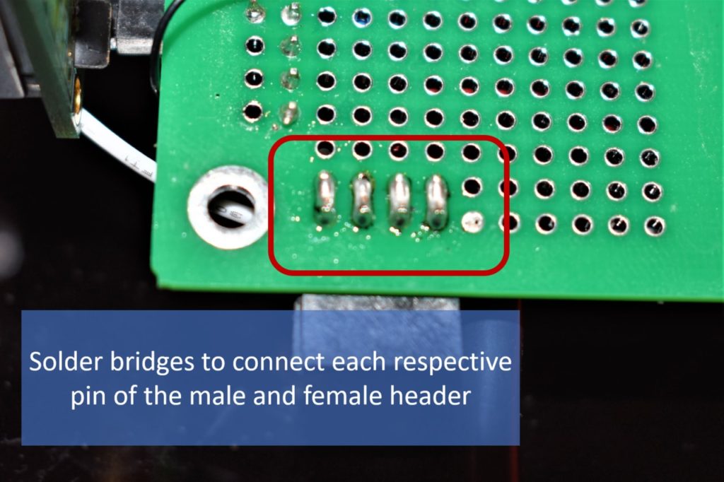
We are mounting the DHT11 sensor to the 2.54mm pitch section of Modulus with a right-angle (R/A) female header, as shown in the image below. Solder the 4-pin R/A female header to the edge of the board. Next, solder a 4-pin male header adjacent to the female header. Once you have the headers soldered on, flip the board over and make a solder bridge between the adjacent pins of the headers.
Wire-wrap the “+” pin to +5Vdc which is any of the pins in column 20 on the 4×26-pin breakout. Then wire-wrap the “-” pin to the GND vector just below the 4×26-pin breakout. Use a 12″ F/M jumper to connect the “OUT” pin to pin 8 of the Uno.
If you are using a breadboard, a wiring schematic is shown below.
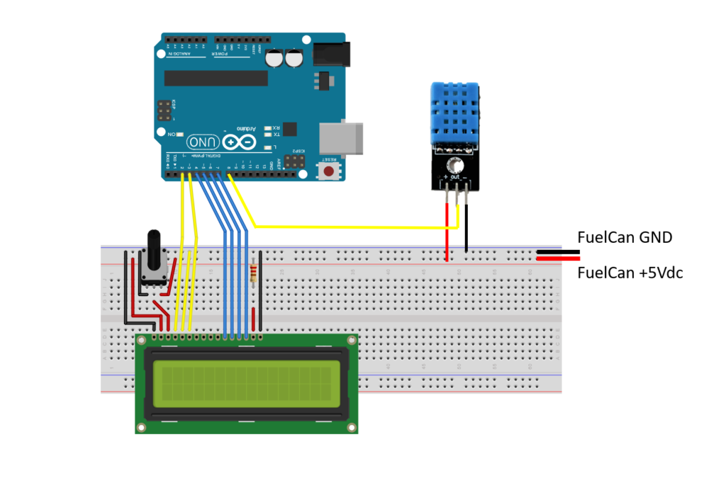
FuelCan Wiring
First, place the breadboard in the bottom storage compartment to limit the length of the jumper wires. You’ll need to supply +5V and GND to the power and ground rails on the breadboard by using the provided banana jack to test-lead clip cables. You will need two male header pins to mount the test-lead clips on the breadboard side. Plug the Type A side of the USB cable into USB1 receptacle and the Type B side into the Uno’s receptacle. Power up the FuelCan with the AC-DC power adapter.
For additional information about the Fuelcan-910, click here or download the user guide.
Software
Once the wiring is complete and the FuelCan is powered up, we can now load the sketch onto the Uno. The first sketch is used with the 16×2 LCD. The second sketch is used with the 20×4 LCD. The DHT11 sensor is sampled every two seconds since sampling faster causes errors.
You’ll need the DHT Library to use the DHT functions within the sketch which is available on Arduino’s website.
About Author
Eric Shea is the founder of ProteShea and is an electrical engineer. He wishes to have a major impact on bridging the gap between engineering theory and real-world applications. He has worked at Kratos Defense, SpaceX, Air Force Research Laboratory, and Polaris Industries. He received a M.S. in electrical engineering from the University of Pittsburgh and a B.S. in electrical engineering from the University of Florida.