7-Segment Display and BCD Decoder
Last updated July 2019
Introduction
In this project, you’ll learn how to interface a 7-segment display to an Arduino Uno. We’ll walk you through different examples such as using a single display to count up and down between 0 and 9, add a switch input to choose whether to count up or down, leverage a BCD (Binary Coded Decimal) decoder to decrease the number of outputs needed on the Uno to drive each LED, and increase the number of 7-segment displays from 1-digit to 4-digit.
Disclaimer
ProteShea, LLC is a participant in the Amazon Services LLC Associates Program, an affiliate advertising program designed to provide a means for sites to earn advertising fees by advertising and linking to Amazon.com
Some links may be affiliate links, in which ProteShea, LLC earns a commission if you use that affiliate link. Please note that this is at no additional cost to you and helps us in creating more content.
Here’s what you’ll need to get started:
- FuelCan
- Modulus or solderless breadboard
- VersaSMT
- Arduino Uno Rev3
- 1-digit and 4-digit 7-segment displays
- (×8) 220Ω resistors
- BCD decoder (surface-mount or through-hole)
- 8″ F/M jumpers
- 30 AWG wire
- 30 AWG wire wrap tool
- Soldering iron
- Solder
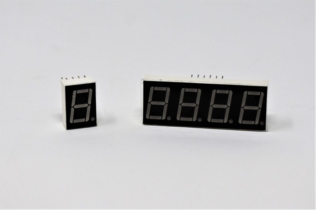
7-Segment Display
The 7-segment display is a cheap alternative to an LCD if you only need to display numbers. They are low-power, have a low-profile, and are easy to use. Further, you can pick between the different number of digits such as 1-digit, 2-digit, and 4-digit displays, depending on how big of a number you want to display. For example, with a 4-digit display, you can display numbers from 0 to 9999.
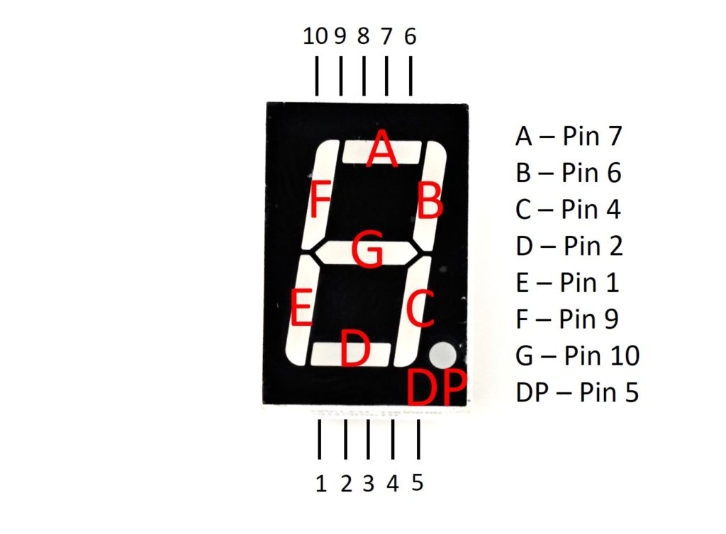
7-segment displays consist of eight LEDs – seven are used to display the number and one is used for the decimal point. They are typically labeled from A to G, and DP for “Decimal Point”, and are mapped to pins 1 through 10, as shown in the image below.
Wait a minute. If each LED consists of an anode and a cathode, how are there only ten pins instead of sixteen? A 7-segment display can be configured one of two ways: 1) Common Cathode where the cathodes of each LED are tied together and 2) Common Anode where the anodes of each LED are tied together. Since they share a common cathode or anode, the pin count is reduced from sixteen to ten pins.
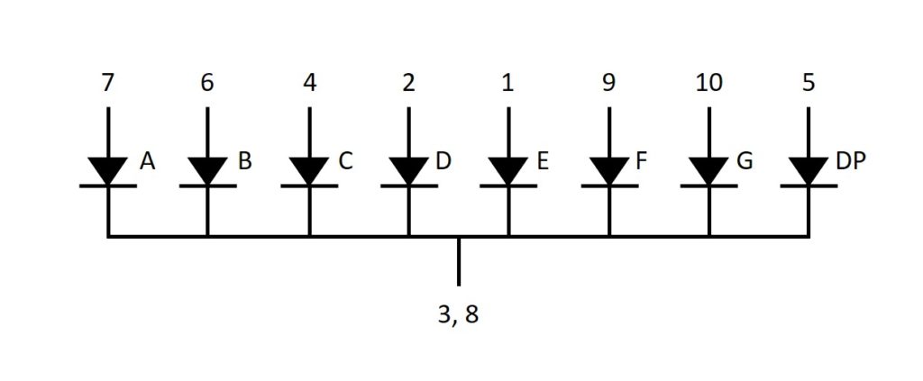
In a Common Cathode configuration, pins 3 and 8 will be wired to ground, and the anodes of each LED will get wired to an output pin on the Uno (each will have a 220Ω resistor in series to limit the current). So, to drive each LED with the Uno, we need to set the output HIGH. This is called active-high since the LED will turn on with a HIGH output. An image of the Common Cathode configuration is shown in the image below.
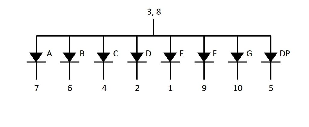
In a Common Anode configuration, pins 3 and 8 will be wired to +5Vdc, and the cathodes of each LED will get wired to an output pin on the Uno (each will have a 220Ω resistor in series to limit the current). To drive each LED with the Uno, we need to set the output LOW. This is called active-low since the LED will turn on with a LOW output. An image of the Common Anode configuration is shown in the image below.
1-Digit 7-Segment Display Wiring
Similar to the LED bar graph that we used in Project 1, each LED needs to have a series resistor to limit the current. Otherwise, the LED will burnout due to overcurrent. To calculate the series resistor, we need to know the forward voltage and forward current of the LEDs. The 7-segment display that we are using has a forward voltage of 3Vdc and a foward current of 10mA. We can use Ohm’s Law to calculate the resistor value, as shown below.
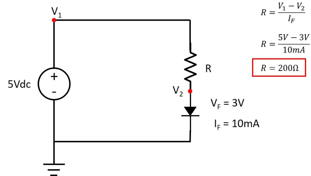
NOTE: we didn’t have a 200Ω resistor on-hand, so we used a 220Ω resistor.
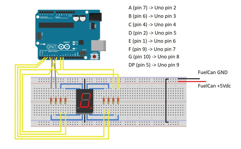
On the Uno, we will need eight digital output pins (pins 2 – 9) to drive each LED. The final circuit schematic is shown in the image below.
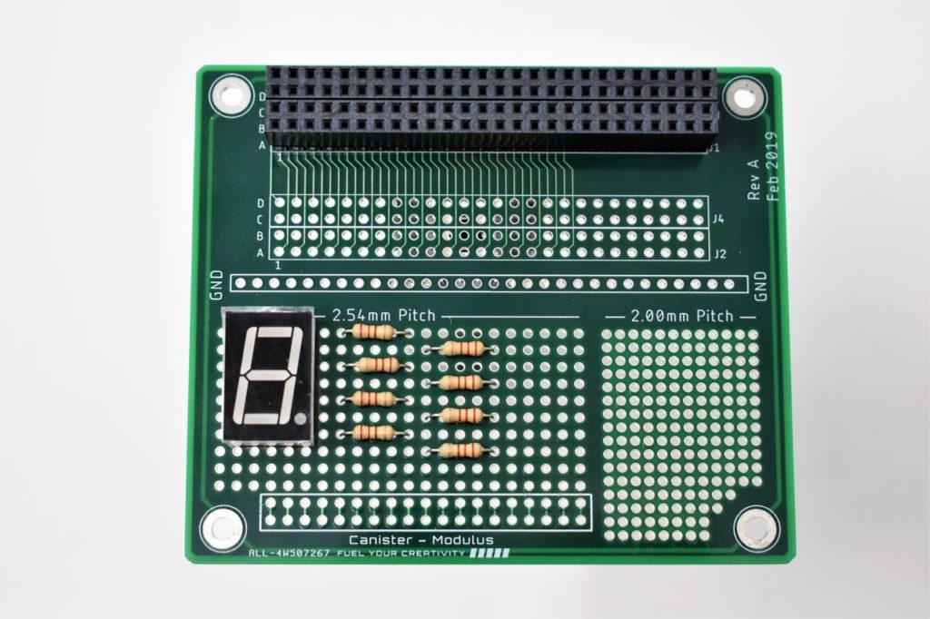
We are using a breadboard to wire the circuit rather than the Modulus Canister since it will take up a good amount of board space. However, feel free to use Modulus if you want to. You will need to use 30 AWG wire and a wire wrap tool. The circuit layout on Modulus will look similar to the image below.
FuelCan Wiring
If you haven’t mounted the Uno onto the prototyping area of the FuelCan, go ahead and do that. If you are using a breadboard instead of Modulus, place the breadboard in the bottom storage compartment to limit the length of the jumper wires. You’ll need to supply +5V and GND to the power and ground rails on the breadboard by using the provided banana jack to test-lead clip cables. You will need two male header pins to mount the test-lead clips on the breadboard side. Plug the Type A side of the USB cable into USB1 receptacle and the Type B side into the Uno’s receptacle. Power up the FuelCan with the AC-DC power adapter.
For additional information about the Fuelcan-910, click here.
Software - Example 1
In the setup() function, pins 2 through 9 are configured as outputs since we need to drive each LED. The loop() function has a single for loop that calls segDisplay() during each iteration, which determines what pins to set as HIGH or LOW with an if statement.
Once the FuelCan is powered up, load the sketch below onto the Uno. The 7-segment display should start counting up between 0 and 9.
Adding a Switch
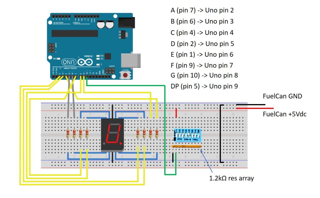
In the previous example, we only used the 7-segment display as an up counter. To choose if we want to count up or down,, we’re going to add a single switch from the switch array that we used in Project 1. The switch is wired as active-high, meaning that when it is ON (switch closed), the output will be HIGH.
We also need a digital input pin on the Uno to read the switch. We will use Uno pin 10. The circuit schematic with a switch added is shown in the image below.
Software - Example 2
The software for example 2 is very similar to example 1. The only difference is that in the loop() function, we call digitalRead(10) to read the switch input. If the switch input is LOW, the display will count up, and if the switch is HIGH, the display will count down.
Load the sketch below onto the Uno and toggle the switch ON and OFF. You should see the display count up when the switch is OFF and count down when the switch is ON.
BCD Decoder
Coming soon.
About Author
Eric Shea is the founder of ProteShea and is an electrical engineer. He wishes to have a major impact on bridging the gap between engineering theory and real-world applications. He has worked at Kratos Defense, SpaceX, Air Force Research Laboratory, and Polaris Industries. He received a M.S. in electrical engineering from the University of Pittsburgh and a B.S. in electrical engineering from the University of Florida.