Control Pan-Tilt with 4-Way Joystick
Last updated May 2019
Introduction
Welcome to ProteShea – in this tutorial, we’ll be showing you how to control a pan-tilt module with a joystick and Arduino Uno. The 4-way joystick consists of four limit switches. Each limit switch has two leads, so we’ll need a total of eight digital I/O pins. The pan-tilt module consists of two servo motors – one for pan and one for tilt. These are controlled via Pulse Width Modulation (PWM), so we’ll need two PWM channels.
Disclaimer
ProteShea, LLC is a participant in the Amazon Services LLC Associates Program, an affiliate advertising program designed to provide a means for sites to earn advertising fees by advertising and linking to Amazon.com
Some links may be affiliate links, in which ProteShea, LLC earns a commission if you use that affiliate link. Please note that this is at no additional cost to you and helps us in creating more content.
Here’s what you’ll need to get started:
4-Way Joystick
The 4-way joystick consists of four limit switches which are pressed when the joystick is moved left, right, up, or down. The switches are normally-open (NO) which means that when the switch is not pressed, the two leads are disconnected internally. When the switch is pressed, the two leads become connected internally.
To do a quick test, use the continuity function on a voltmeter. Place one probe on one lead and the other probe on the second lead of the limit switch. You should not have continuity. Now, move the joystick to press the limit switch that you are probing. You should have continuity.
An animation is shown below that illustrates which limit switch is pressed when the joystick is moved in a particular direction. For example, when the joystick is moved up, limit switch 3 is pressed.

Pull-Down Resistors
Pull-down resistors must be used on the output side of each limit switch to prevent a floating input pin that is connected to the Uno. A floating pin means that the signal level can randomly switch between +5V (if this is your high signal voltage) and GND. This can cause the Uno to think that the switch is activated, and it will perform the function accordingly. For example, let’s say we have a piece of code that checks if a digital input is high and if it is, an LED will turn on. If the digital input is low (what we want as our default state), the LED will remain OFF. If the input is floating, the pin could randomly go high and cause the LED to turn ON even though the switch is off.
The schematic below shows a pull-down resistor connected to the output of a switch (input to Uno). When the switch is not pressed (OFF), the output will be pulled to GND. When the switch is pressed (ON), the output will be pulled to +5V.

Pulse Width Modulation
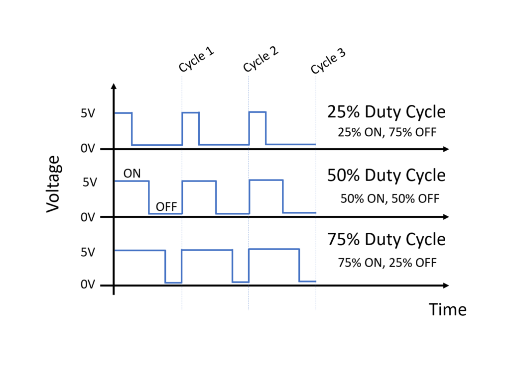
PWM is used in a wide variety of applications such as robotics and control. It is a way to vary the output voltage to a load similar to how an analog signal can vary. A digital output can be high (usually +5 or +3V3) or low (GND). To vary the voltage, we have to change something called the duty cycle. Duty cycle is the ratio of ON vs OFF time in one cycle. For example, a 50% duty cycle would mean that the signal is ON for 50% and OFF for 50% of one cycle. If we have a 75% duty cycle, the signal is ON for 75% and OFF for 25% of one cycle.
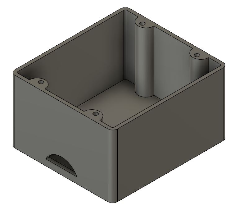
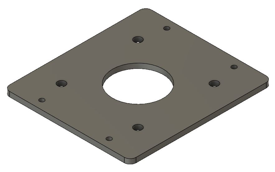
Mechanical Enclosure
The joystick does not come with a mechanical enclosure to mount it into, so we have to design our own. We used a 3D printer to make ours, or you could also make it out of acrylic. We also redesigned the aluminum top plate to give more clearance for the limit switches. This was manufactured with a piece of 1/8″ thick acrylic and a laser cutter.
Wiring the Joystick
The limit switches on the joystick do not come prewired. You can either use female quick disconnects or solder wire straight to the leads. We opted to solder wire straight to the leads instead of using quick disconnects. We used 30 AWG wire since there is not much current flowing through the wire, but you can use anywhere between 24 – 30 AWG wire. If you can, try to label or color code each wire so that it is easier to identify which wire goes to which limit switch on the joystick. Otherwise, you will be probing each wire with a voltmeter to determine which wire is what.
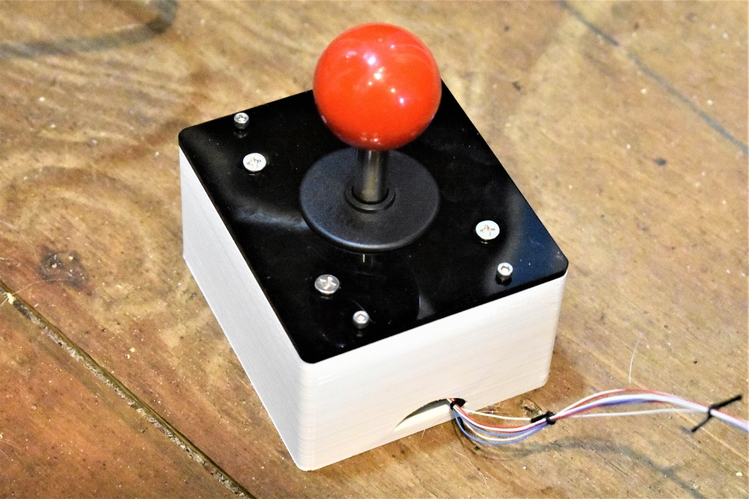
Cut each wire to 2′ in length. You can shorten or lengthen them depending on how long you want your wire harness to be. Strip about a 1/2″ of insulation off of each wire. Next, solder a wire to each lead of the limit switches. To prevent short circuits from one lead to an adjacent lead, add a piece of heat shrink as shown in the image below. Once each wire is soldered on, pass them through the hole in the enclosure and mount the joystick to the enclosure.

On the end of each wire, crimp on a male crimp pin so it is easier to stick into a hole on the breadboard. The 30 AWG wire is too fragile without the crimp pin. One benefit of using thicker gauge wire is that you most likely wouldn’t need the male crimp pins. We also added a piece of heat shrink to the ends of each wire. Insert the crimp pins into the breadboard, or straight into the female header on the Uno if your wire harness is long enough.
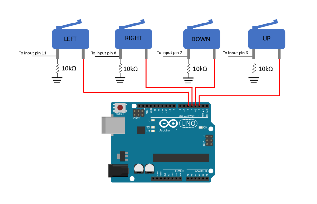
Hopefully you labeled which wire goes to each limit switch. We’re using Uno pins 2-5 as output pins and pins 6-8, and 11 as input pins on the Uno. The wires that go to the input pins of the Uno will need to be routed to a breadboard first so that they can be tied to a pull-down resistor. A schematic is shown below.
Wiring the Servos
Servo motors typically have 3 wires: power (red), ground (black or brown), and signal (yellow). They have a 3-pin female header at the end of the wiring harness so we’ll need 3 male header pins to connect them to a breadboard. You can either route the signal wire of each servo motor to the breadboard first or tie them straight to the female header on the Uno. We’re going to use pins 9 and 10 since these are PWM channels (marked with ‘~’ on the Uno). The servo used to tilt the camera will be tied to pin 10 and the servo used to pan the camera will be tied to pin 9. A circuit schematic is shown below.

FuelCan Setup
I placed the breadboard in the bottom storage compartment to limit the length of the jumper wires and mounted the Arduino Uno to the FuelCan’s prototyping area. We need to supply GND to the ground rail and +5V to the positive rail on the breadboard. Use the provided banana jack to test-lead clip cables to do so. You will need two male header pins to mount the test-lead clips to the breadboard side. Plug the Type A side of the USB cable into the USB1 receptacle and the Type B side into the Uno’s receptacle. Plug in the Type A to Type A USB cable into a USB port on your computer and the external USB connector of the FuelCan. Power up the FuelCan with the AC-DC power adapter.
For additional information about the Fuelcan-910, click here or download the user guide.
Software
Once the wiring is complete and the FuelCan is powered up, we can now load the sketch onto the Uno. The sketch is below. When the joystick is moved up, down, left, and right, the camera will tilt up, tilt down, pan left, and pan right, respectively. If yours does not do this, try rearranging the input wires from the limit switches.
About Author
Eric Shea is the founder of ProteShea and is an electrical engineer. He wishes to have a major impact on bridging the gap between engineering theory and real-world applications. He has worked at Kratos Defense, SpaceX, Air Force Research Laboratory, and Polaris Industries. He received a M.S. in electrical engineering from the University of Pittsburgh and a B.S. in electrical engineering from the University of Florida.