Air Valve and a 1-Channel Relay Module
Last updated May 2019
Introduction
Welcome to ProteShea – in this tutorial, we’ll be connecting a 1-channel relay module to the Arduino Uno to control an electric solenoid air valve. The reason why we need a relay module is because the valve pulls 500 mA at +12Vdc. Similar to the current limitation discussed in Project 5, the Uno cannot source enough current (only 40 mA max) to power the valve. Let’s knock down some dominoes!
Disclaimer
ProteShea, LLC is a participant in the Amazon Services LLC Associates Program, an affiliate advertising program designed to provide a means for sites to earn advertising fees by advertising and linking to Amazon.com
Some links may be affiliate links, in which ProteShea, LLC earns a commission if you use that affiliate link. Please note that this is at no additional cost to you and helps us in creating more content.
Here’s what you’ll need to get started:
Relay Module
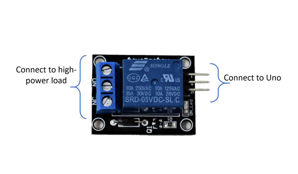
The relay module we’re using is 1-channel. There are other options such as a 2-channel relay which consists of two 1-channel relays on a single PCB. There are two sides on the relay: one that contains a 3-pin terminal block and one that contains a 3-pin male header as shown below. The terminal block is used to connect the high-power load and the 3-pin male header is used to connect to the Uno.
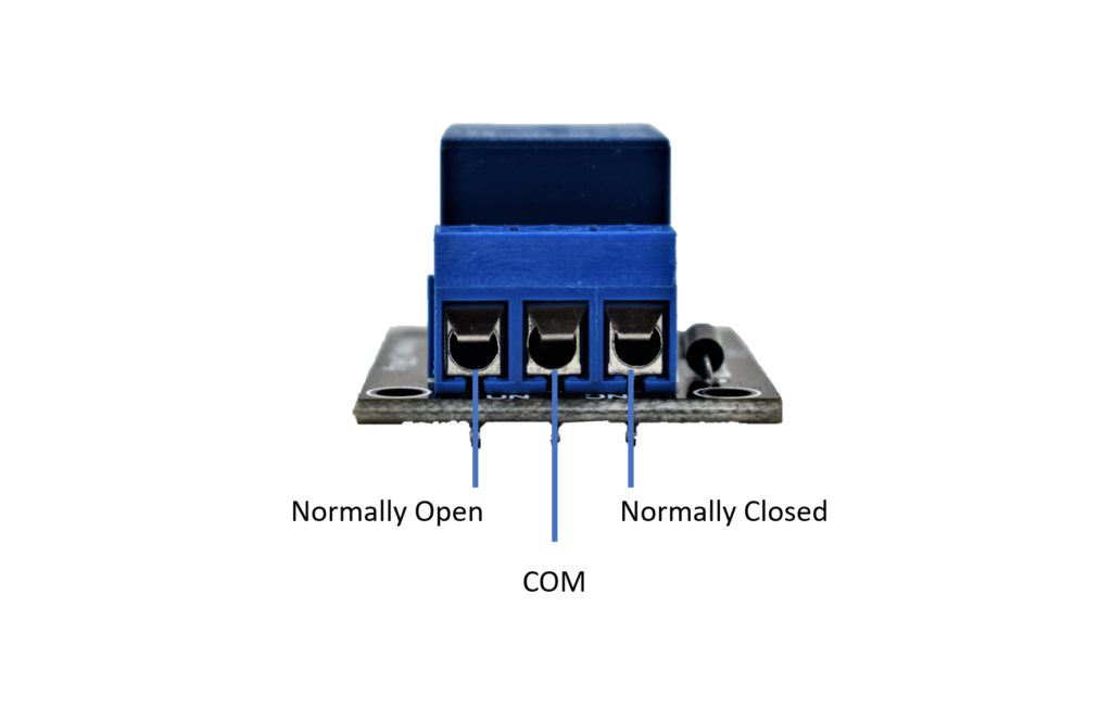
First, we’ll explain the 3-pin terminal block. The 3 pins from left to right are normally closed (NC), common (COM), and normally open (NO). The pin assignments may vary from relay to relay, but you can quickly determine which pins are NO or NC. To do so, set your voltmeter to do a continuity check. Place one probe on the middle-pin block and the other probe on the left-pin block. If there is continuity, the left pin is NC. If not, the left pin is NO. The pin assignments for the terminal block that we’re using are shown below.
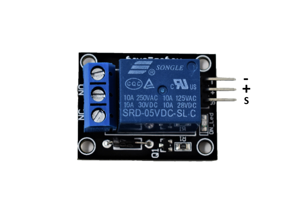
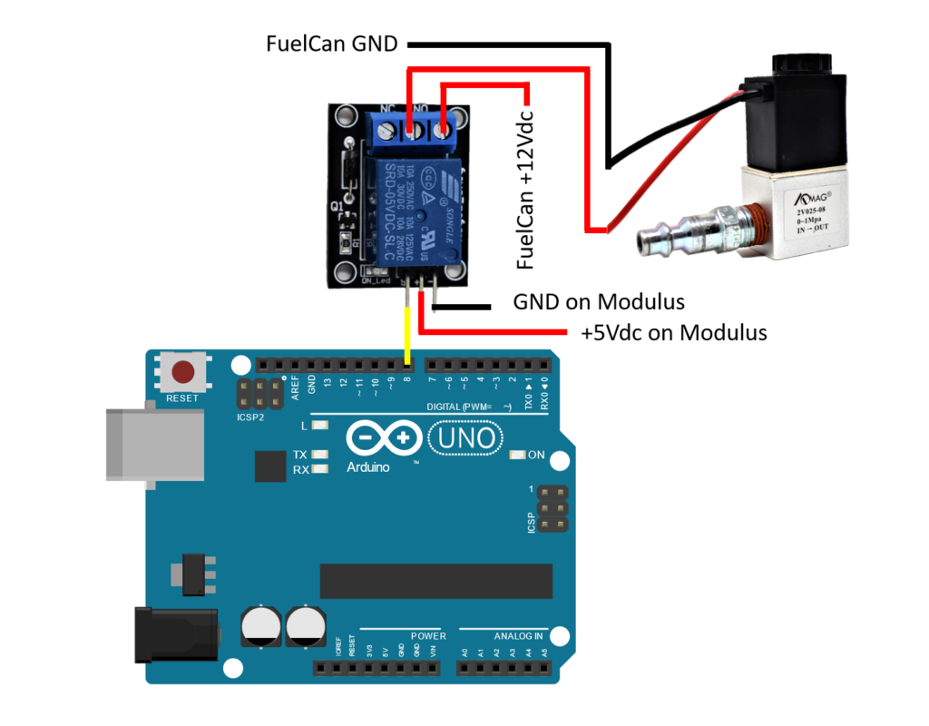
Next, we have the 3-pin right-angle male header which is used to connect to the Uno. The pins are labeled as “+”, “-“, and “S” which are shown below. We need to connect “-” pin to GND, the “+” pin to +5Vdc, and “S” to any of the Uno’s digital I/O pins – we connected it to pin 8.
Electric Solenoid Air Valve
The air valve contains a solenoid to control the opening and closing of the valve. A solenoid consists of a coil of wire and when a current passes through the coil, a magnetic field is induced. This magnetic field causes the shaft to move inside of the coil. When the solenoid is energized, the shaft moves up causing the valve to open. When the solenoid is de-energized, the shaft moves back down causing the valve to close.
The ignition on a vehicle or outboard motor uses a solenoid to start the engine. When you turn the key, a current is sent through the coil of the solenoid which causes the rod to engage and turn the flywheel. Once the engine starts, the solenoid is de-energized and the rod disengages the flywheel.
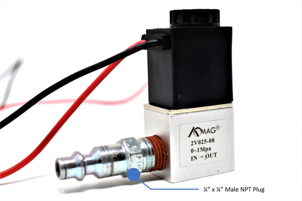
The air valve has an inlet valve and an outlet valve and the direction of the air flow is on the valve so you can easily identify it. Each side contains a 1/4″ NPT threads which is common for pneumatic systems such as an air compressor. We used a 1/4″ x 1/4″ male NPT plug for the inlet side to connect an air hose and kept the outlet side as is. An image is shown below.
Modulus
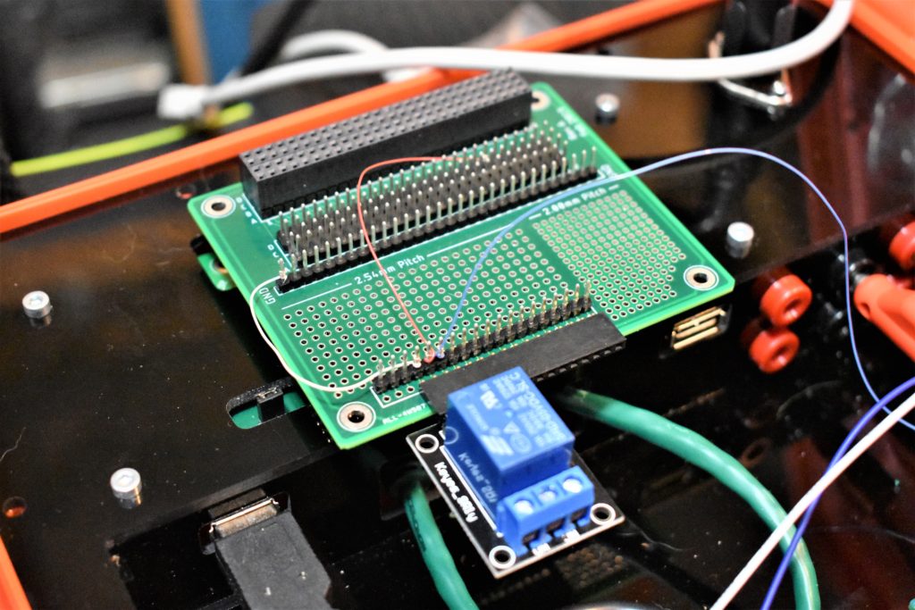
We are using Modulus to mount the relay to. If you have not soldered on anything to your Modulus Canister, please watch this video on our basic layout. We will be inserting the relay into the right-angle female header which is soldered to the 1-to-1 link. Then, we’ll wire wrap the – and + pins to GND and +5Vdc on Modulus, respectively. Please consult the FuelCan User Guide to determine the pinout of the 4×26-pin connector. We’ll use an 8″ F/M jumper to route the S pin on the relay to pin 8 on the Uno. An image is shown below with our setup.
Air Valve Wiring
Okay, we have one side of the relay connected. We now have to connect the air valve to the relay’s terminal block. The air valve requires +12Vdc and 500 mA which can be supplied by the FuelCan’s +12Vdc rail. The red wire will connect to the COM pin on the relay’s terminal block and the black wire will be connected to GND. An image is below for reference. Cut a 2″ piece of 20 AWG wire and strip 1/4″ of insulation off of both ends. Unscrew the NC terminal with a small flathead screwdriver and insert the 2″ piece of wire. Screw the terminal block screw back down to clamp the wire in. Make sure that you clamp down on the wire and not the insulation. Next, unscrew the COM terminal block screw, insert the red wire of the air valve, and clamp the wire into place.
Insert one of the banana cables into the +12Vdc female banana jack on the FuelCan and attach the test-lead clip to the 2″ piece of wire that is sticking out of the NC terminal block. Insert another banana cable into the GND female banana jack on the FuelCan and attach the test-lead clip to the black wire of the air valve.
Final Steps
First, let’s go ahead and mount the Arduino Uno to the FuelCan’s prototyping area. Plug the Type A side of the USB cable into USB1 receptacle and the Type B side into the Uno’s receptacle. Plug the Type A to Type A USB cable into a USB port on your computer and the external USB connector of the FuelCan. Power up the FuelCan with the AC-DC power adapter.
For additional information about the Fuelcan-910, click here or download the user guide.
The last thing to do besides the software is to attach the air hose to the air valve. Set the regulator on the air compressor to 115 PSI. If you go above this, you could damage the air valve. Go ahead and turn the air compressor on while we load the software.
Software
Once the wiring is complete and the FuelCan is powered up, we can now load the sketch onto the Uno. The sketch is below. The air valve will open every 3 seconds and then close immediately.
About Author
Eric Shea is the founder of ProteShea and is an electrical engineer. He wishes to have a major impact on bridging the gap between engineering theory and real-world applications. He has worked at Kratos Defense, SpaceX, Air Force Research Laboratory, and Polaris Industries. He received a M.S. in electrical engineering from the University of Pittsburgh and a B.S. in electrical engineering from the University of Florida.