LED Bar Graph and Switch Array
Last updated April 2019
Introduction
Welcome to ProteShea – this is our first project write-up for the Arduino Uno! In this tutorial, we’ll be interfacing a LED and switch array to the Arduino Uno (revision 3). We’ll use 9 out of 10 LEDs on the bar graph and 5 out of 8 switches on the switch array, maxing out the Uno’s GPIO! Each switch will control a different light sequence on the LED bar graph.
Disclaimer
ProteShea, LLC is a participant in the Amazon Services LLC Associates Program, an affiliate advertising program designed to provide a means for sites to earn advertising fees by advertising and linking to Amazon.com
Some links may be affiliate links, in which ProteShea, LLC earns a commission if you use that affiliate link. Please note that this is at no additional cost to you and helps us in creating more content.
Here’s what you’ll need to get started:
- FuelCan
- Modulus or solderless breadboard
- LED bar graph, switch array, and the 470 ohm and 1.2k ohm resistor arrays from the Modulus Kit
- Arduino Uno Rev3
- 6″ M/M jumpers
LED Bar Graph
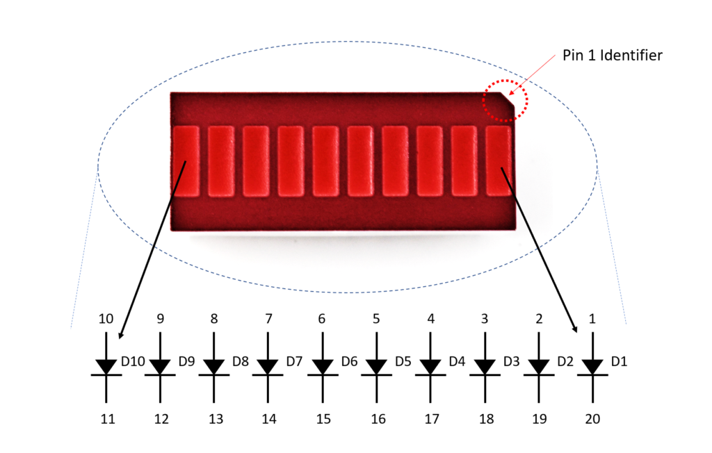
The LED bar graph consists of a vector of independent LEDs. The number and color of the LEDs can vary, but we’ll be using a red, 10-segment bar graph. The internal circuit and pin assignments are shown in the image below. Each LED is oriented the same internally, so the anodes are pins 1-10 and the cathodes are pins 11-20.
To limit the current passing through each LED, we’ll be using a 470 ohm, 9-resistor array. If you do not place a resistor in series with the LED, you are essentially shorting power to ground and could damage the LED or power supply.
There are two important numbers to look for in the LED’s datasheet. The first one is the forward voltage which is the voltage drop across the LED. This is usually given as a maximum rating, so you want to make sure to keep the voltage at or below the forward operating voltage. The second is the forward current which is the maximum current that should be sourced to the LED. For example, the forward voltage and current for each LED in the bar graph is 2.6V and 25mA, respectively. The circuit for one LED is shown below.
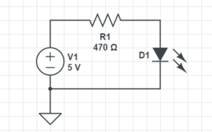
The 470 ohm resistor is a little big when connecting to a 5V source. The current through the LED will be around 5mA, but the LED is still bright enough. We did this because the FuelCan does provide +12V, so if you wanted to use that rail for the LEDs, you’d still be under the forward current rating.
You can place the resistor before (as shown above) or after the LED. It will still limit the amount of current sourced through the LED.
Switch Array
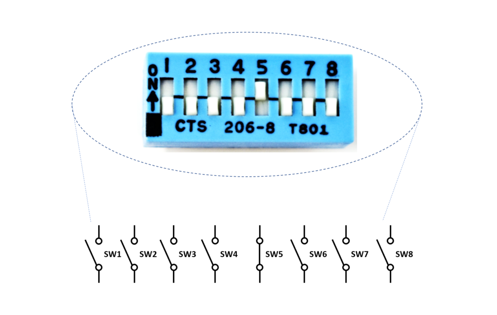
The switch array varies in the number of switches and type – we’ll be using an 8-position SPST (single-pull double-throw) slide switch. A schematic of the switch array is shown below. Notice that when the switch is in the OFF position, the switch is open. When the switch is in the ON position, such as switch 5, the switch is closed. Similar to the LED, we also want to limit the current passing through the switch to prevent damage and minimize power consumption.
When you’re consulting the documentation for the switch, you want to look for the max voltage and current. For example, the max voltage and current for this switch array is 24V and 50mA, respectively. We’ll be using a 1.2k ohm resistor in series with each switch array, and the +5V supply on the FuelCan. This means that the current passing through the switch will be ~4.2mA (I = V/R = 5/1.2k). The circuit schematic is shown in the image below.
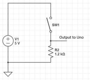
Let’s say we chose a smaller resistor value, 680 ohms. The current through the switch would be ~7.4mA (I = 5/680), still under the max current rating of the switch. But, we would have a higher power consumption. Power is equivalent to the voltage multiplied by the current (P = V x I), so the power consumption for using the 1.2k ohm and 680 ohm resistor would be 20.8mW and 36.7mW, respectively. This may not seem like a big difference, but when you are designing low-power applications, this difference is huge.
Resistor Array
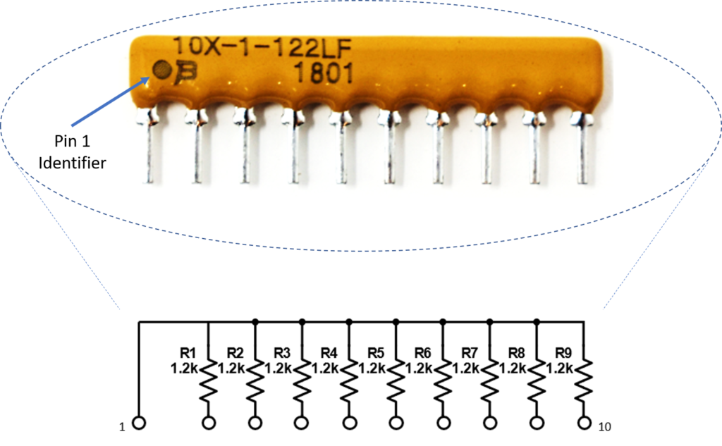
The resistor array is made up of a number of bussed (one lead of each resistor shares a common node with the other resistors in the array) resistors, in this case, 9 resistors. These are beneficial for adding a series resistor to multiple, identical components such as the LED bar graph or the switch array. They also help with keeping your wiring clean and compact. The internal circuitry of the 1.2k ohm resistor array is shown in the image below (the 470 ohm array has a similar internal circuitry). When you look at the resistor array, pin 1 is identifiable with the dot. This can be connected to power or ground, but make sure to consult the datasheet for the max voltage rating if you are connecting it to power.
Wiring
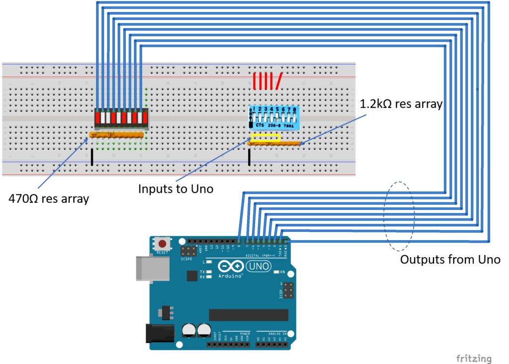
I’m using a breadboard instead of Modulus since almost everybody has a breadboard. First, let’s place the LED bar graph and switch array onto the breadboard. Insert both so that the body is over the valley of the breadboard. You do not want the pins to short each other by being connected to the same node. Next, place the 470 ohm resistor array on the cathode side of the LED and tie pin 1 of the array to GND. Make sure that pin 1 of the resistor array is not connected to any of the cathodes of the LED bar graph. Since the bar graph has 10 LEDs and the resistor array only has 9 resistors, we can only use 9 out of 10 LEDs.
Next, use a M/M jumper to wire the anode side of the LED bar graph as outputs to the Uno pins 0-8. For example, pin 10 of the bar graph will get wired to Uno pin 0, pin 9 of the LED will get wired to Uno pin 1, and so on.
Place the 1.2k ohm resistor array as shown in the image below. Tie pin 1 of the array to GND, and make sure it does not connect to any of the switch pins on the switch array. The breadboard holes outlined in yellow will be tied to Uno pins 9-14. For example, switch 1 will be wired to pin 9, switch 2 will get wired to pin 10, and so on. Tie the other switch pins, 1-5, to +5V.
FuelCan Setup
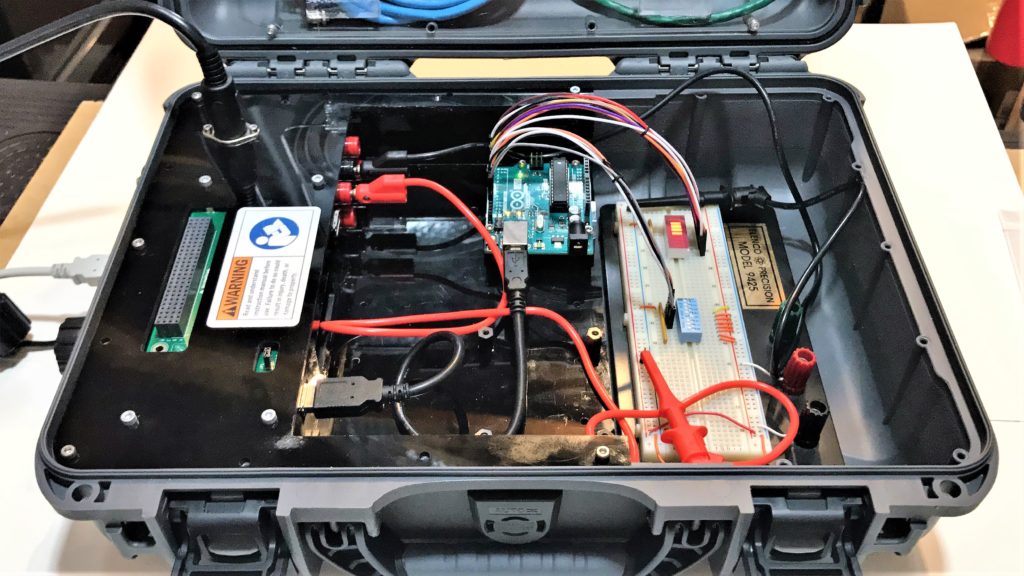
I placed the breadboard in the bottom storage compartment to limit the length of the jumper wires. In order to supply +5V and GND to the power and ground rails on the breadboard, use the provided banana jack to test-lead clip cables. You will need two male header pins to mount the test-lead clips to the breadboard side. Plug the Type A side of the USB cable into USB1 receptacle and the Type B side into the Uno’s receptacle. Power up the FuelCan with the AC-DC power adapter.
The figure below shows the final system for interfacing a LED and switch array to the Arduino Uno.
For additional information about the Fuelcan-910, click here or download the user guide.
Software
Once the wiring is complete and the FuelCan is powered up, we can now load the sketch onto the Uno. The sketch is below. To change the LED function, simply change switches 1-5 to the ON position. If there are multiple switches in the ON position, the LED function will take priority based on the lowest switch number. For example, if switches 1 and 3 are ON, the LED function will be the one mapped to switch 1.
About Author
Eric Shea is the founder of ProteShea and is an electrical engineer. He wishes to have a major impact on bridging the gap between engineering theory and real-world applications. He has worked at Kratos Defense, SpaceX, Air Force Research Laboratory, and Polaris Industries. He received a M.S. in electrical engineering from the University of Pittsburgh and a B.S. in electrical engineering from the University of Florida.
Categories
About Author
Eric Shea is the founder of ProteShea and is an electrical engineer. He wishes to have a major impact on bridging the gap between engineering theory and real-world applications. He has worked at Kratos Defense, SpaceX, Air Force Research Laboratory, and Polaris Industries. He received a M.S. in electrical engineering from the University of Pittsburgh and a B.S. in electrical engineering from the University of Florida.
Great article that teaches the basics!