MPU6050 Accelerometer and Gyroscope
Last updated July 2019
Project 19
1. Introduction
2. 16×2 LCD
3. MPU6050
4. Adapticon
7. Breadboard
10. Gyroscope Data
11. Data Fusion
12. Yaw Drift
Introduction
Welcome to ProteShea – in this project, we’re going to show you how to interface a MPU6050, accelerometer and gyroscope to the Arduino Uno (rev 3). The overall purpose of the MPU6050 is to determine the angular position of an object. We’ll show you how the sensor works and how to communicate with it via I2C. The MPU6050 can be embedded into applications such as a gimbal, self-balancing robot, UAV (unmanned aerial vehicle), weather balloon, satellite, or even a vehicle to deploy airbags in a car crash.
Everybody loves some stability in life, why not activate stability in your electronics?
Disclaimer
ProteShea, LLC is a participant in the Amazon Services LLC Associates Program, an affiliate advertising program designed to provide a means for sites to earn advertising fees by advertising and linking to Amazon.com
Some links may be affiliate links, in which ProteShea, LLC earns a commission if you use that affiliate link. Please note that this is at no additional cost to you and helps us in creating more content.
Here’s what you’ll need to get started:
16x2 Character LCD
Please see Project 9 to learn more about how the LCD works and how to interface the 16×2 LCD in 4-bit mode. Since we need to use an interrupt pin on the Uno, we have to change the wiring for the LCD. This is because the Uno’s interrupts are only available on pins 2 and 3. So, instead of using Uno pins 2 – 7 to interface the LCD, we’re going to shift to pins 8 – 13. As a result, you should have pins 4, 6, and 11-14 of the LCD connected to Uno pins 8, 9, and 10 – 13, respectively. The LCD is mounted to the Modulus Canister via the 16-pin, right-angle female header soldered to the 1-to-1 link, as shown in the image below. We recommend wire wrapping 30 AWG wire to the male header pins so you can stack Adapticon (used to mount the MPU6050) on top of Modulus.
MPU6050 Accelerometer and Gyroscope
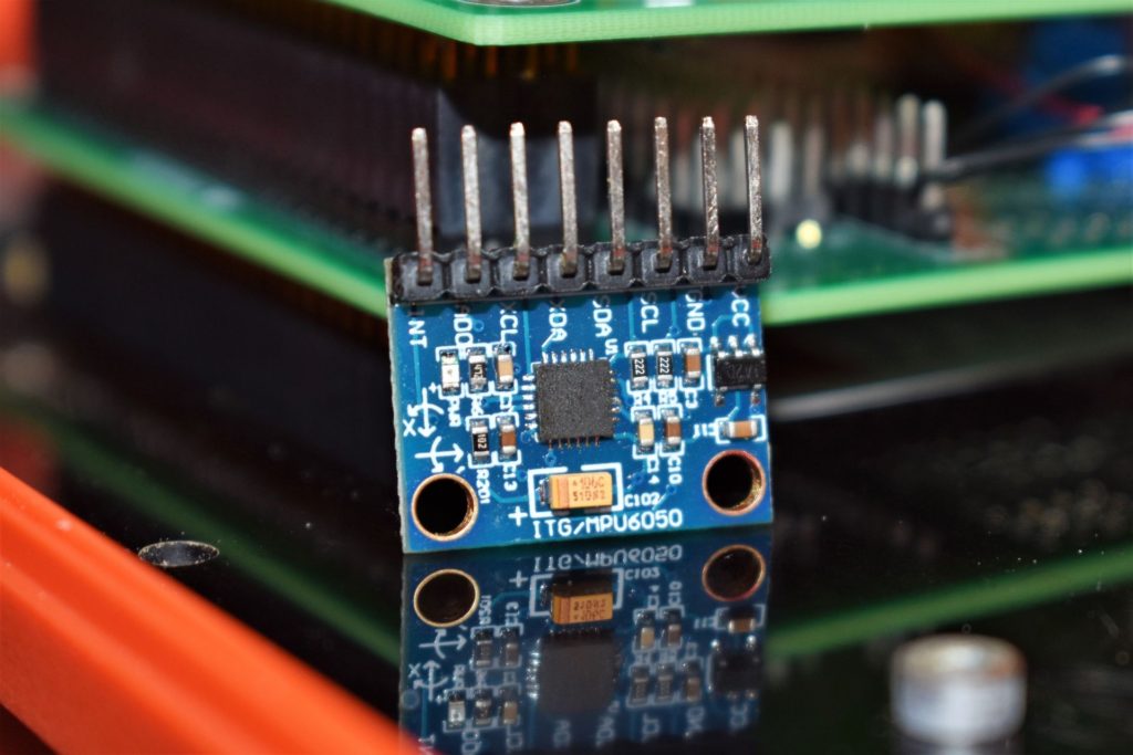
The MPU6050 is a 6-axis IMU (inertial measurement unit) that contains a 3-axis accelerometer and a 3-axis gyroscope. Both of these sensors operate via MEMS (Micro-Electro Mechanical Systems) technology and are manufactured with microfabrication techniques. That means that these devices will range in size from below one micron (one-millionth of a meter) to several millimeters. In order to pack an accelerometer and a gyroscope inside the same chip, the MEMS system is on the micron scale. You can see the single IC in the image below.
Accelerometers can be manufactured based on different techniques. The first technique is called the piezoelectric effect, which works with microscopic crystal structures. When these structures experience a force, a voltage is generated based on the magnitude of the force. The second technique uses two microstructures. When the microstructures are static (no external force exerted on the sensor), there is a certain capacitance between them. When a force is applied, the microstructures move and causes a change in capacitance. This capacitance is measured and processed to correspond to a certain acceleration. Whichever technique an accelerometer uses, the gravitational acceleration along all three axes can be calculated, and the angle at which the sensor is positioned can be known. The MPU6050’s accelerometer has a user-programmable range of ±2g, ±4g, ±8g, and ±16g.
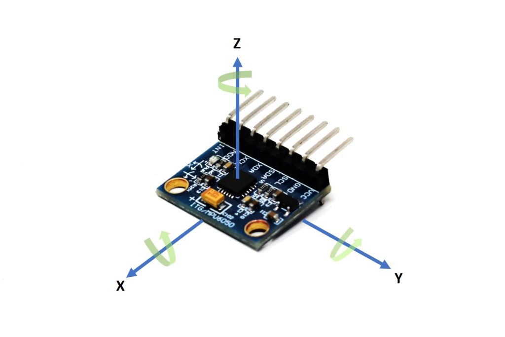
A gyroscope works on the principles of the Coriolis effect where an external force causes the mass moving in a rotating system to move perpendicular to both the direction of motion and the axis of rotation. This perpendicular displacement causes a change in the capacitance between the microstructures which can be measured and processed. The gyroscope measures angular velocity which has units in degrees per second. For example, if you have a wheel that spins once per second, it has an angular velocity of 360 degrees per second. The axes relative to the module are shown in the image below. The MPU6050’s gyroscope has a user-programmable range of ±250, ±500, ±1000, and ±2000°/sec (DPS).
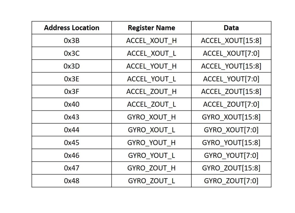
To communicate with the module, we have to use I2C. The IC has over 80 addressable registers, but luckily we only have to read and write from a few. The registers that hold the accelerometer and gyroscope data are shown in the table below. Each measurement is 16 bits, and each register can hold 8 bits, which is why there are _H and _L registers. For example, if we want to obtain the accelerometer value for the x axis, we would have to read registers 0x3B and 0x3C for the upper and lower bytes, respectively.
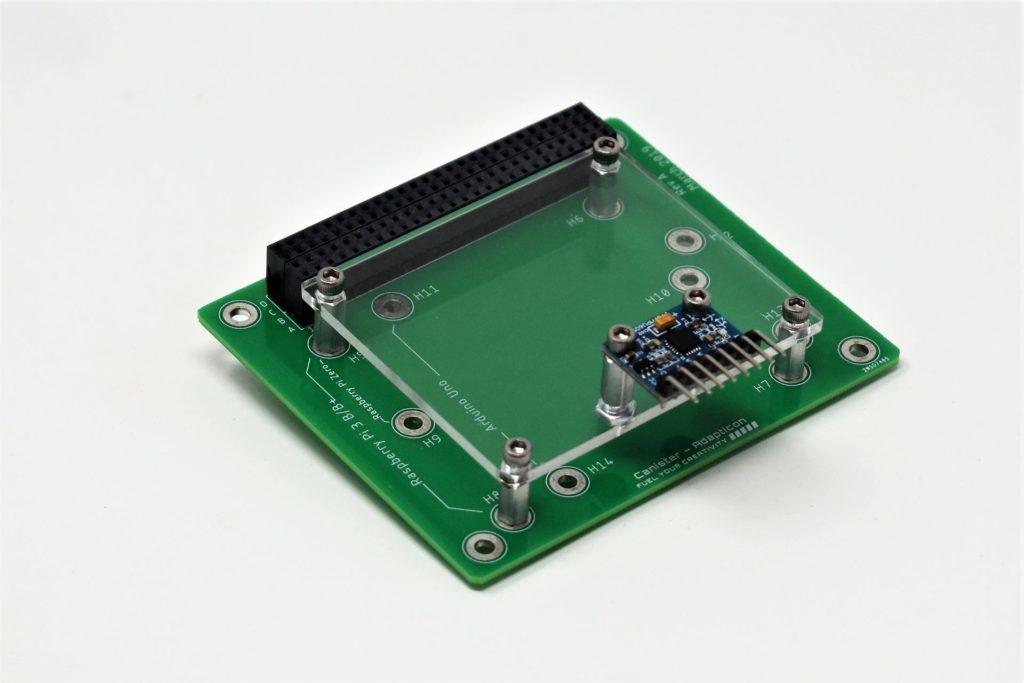
Mounting the MPU6050 to Adapticon
In this section, we are going to show you how to mount the MPU6050 to Adapticon. The other options are to insert the module into a solderless breadboard or insert it into a right-angle male header that is soldered on to Modulus. If you are not mounting it to Adapticon, you can skip this section.
To mount the module to Adapticon, you will need to make an adapter plate – the .step file is downloadable via the link below. We made ours out of 1/8″ acrylic and used a laser cutter to manufacture it. You could also use a CNC router to cut the acrylic or manufacture the plate with a 3D printer.
Once the adapter plate is manufactured, insert the #4-40 x 3/8″ M/F hex standoffs into the hole designators for the Raspberry Pi 3 (H5, H6, H7, H8) and screw on a #4 hex nut to secure each standoff. Also, insert a #4-40 x 3/8″ M/F hex standoff into the holes that are located in the middle near the edge of the plate, and secure each one with a #4-40 hex nut. Use #4-40 socket head screws to mount the MPU6050 to the hex standoffs. Then, use #4-40 socket head screws to mount the adapter plate to Adapticon.
Canister Stack
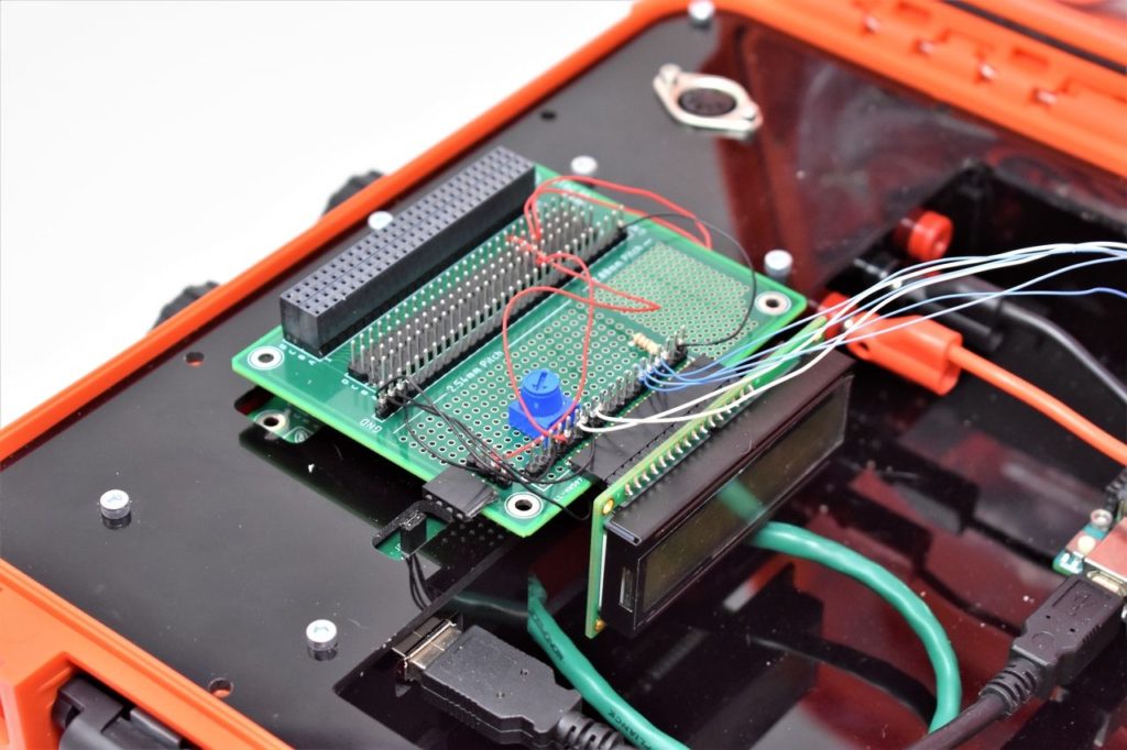
After you have the MPU6050 mounted to Adapticon, we can proceed with connecting the Canisters together to create the Canister stack. Mate Adapticon to Modulus by carefully aligning the male pins of Adapticon with the 4×26-pin female connector of Modulus and pressing the two boards together. Then, insert the stack into the 4×26-pin female connector on the FuelCan. An image of the final assembly is shown below.
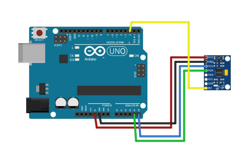
Wiring the MPU6050
The MPU6050 module consists of 7 pins that are broken out: VCC, GND, SCL, SDA, XDA, XCL, ADO, and INT. You can use M/F jumper wires or 30 AWG wire wrap. Connect VCC and GND to +5Vdc and GND pins on the 4×26-pin female connector, respectively. We used pin A20 for +5Vdc and A21 for GND. Next, connect SCL and SDA to Uno pins A5 and A4, respectively. Finally, connect INT to pin 2 on the Uno. A wiring diagram is shown in the image below.
NOTE: The MPU6050 can be addressable at addresses 0x68 and 0x69 via the AD0 pin. If it is left unconnected, the I2C address will be 0x68, and if it is wired to VDD, the address will be 0x69. This is useful if you want to have two MPU6050s on the I2C bus.
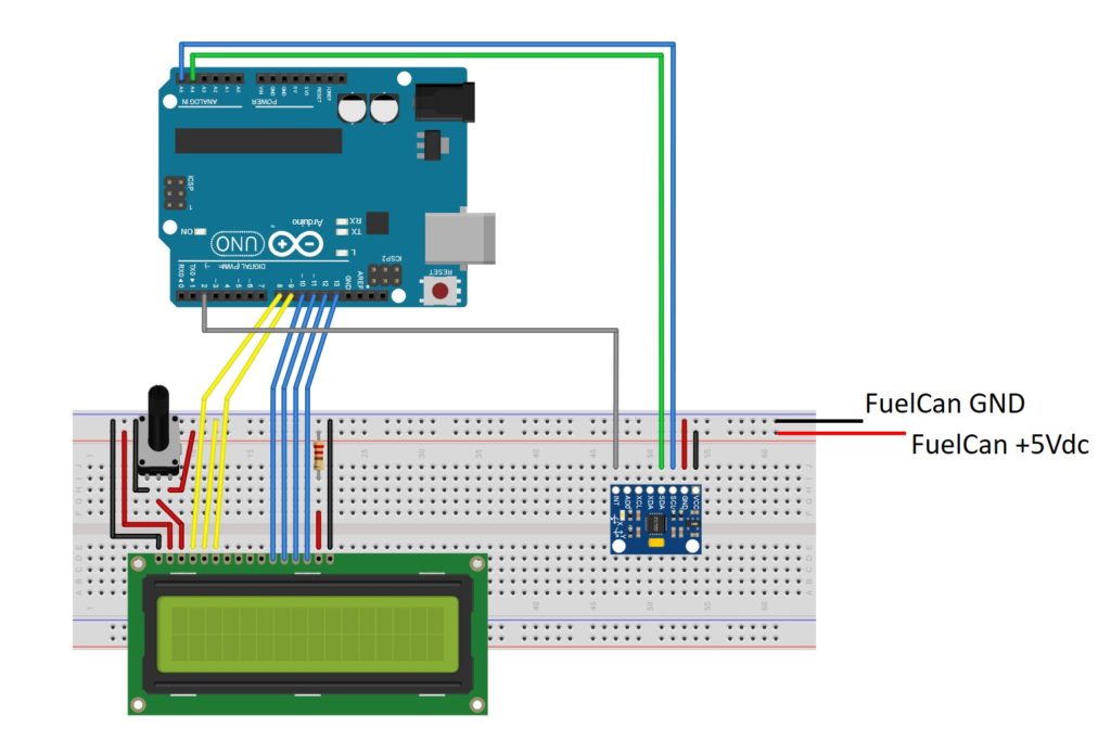
Solderless Breadboard
If you are using a solderless breadboard, use the schematic below to make the necessary connections with M/M jumper wires. To supply power to the breadboard, please see the next section.
FuelCan Wiring
If you haven’t mounted the Uno onto the prototyping area of the FuelCan, go ahead and do that. If you are using a breadboard instead of Modulus and Adapticon, place the breadboard in the bottom storage compartment to limit the length of the jumper wires. You’ll need to supply +5Vdc and GND to the power and ground rails on the breadboard by using the provided banana jack to test-lead clip cables. You will need two male header pins to mount the test-lead clips on the breadboard side. Plug the Type A side of the USB cable into the USB1 receptacle and the Type B side into the Uno’s receptacle. Plug in the AC-DC power adapter to power up the FuelCan.
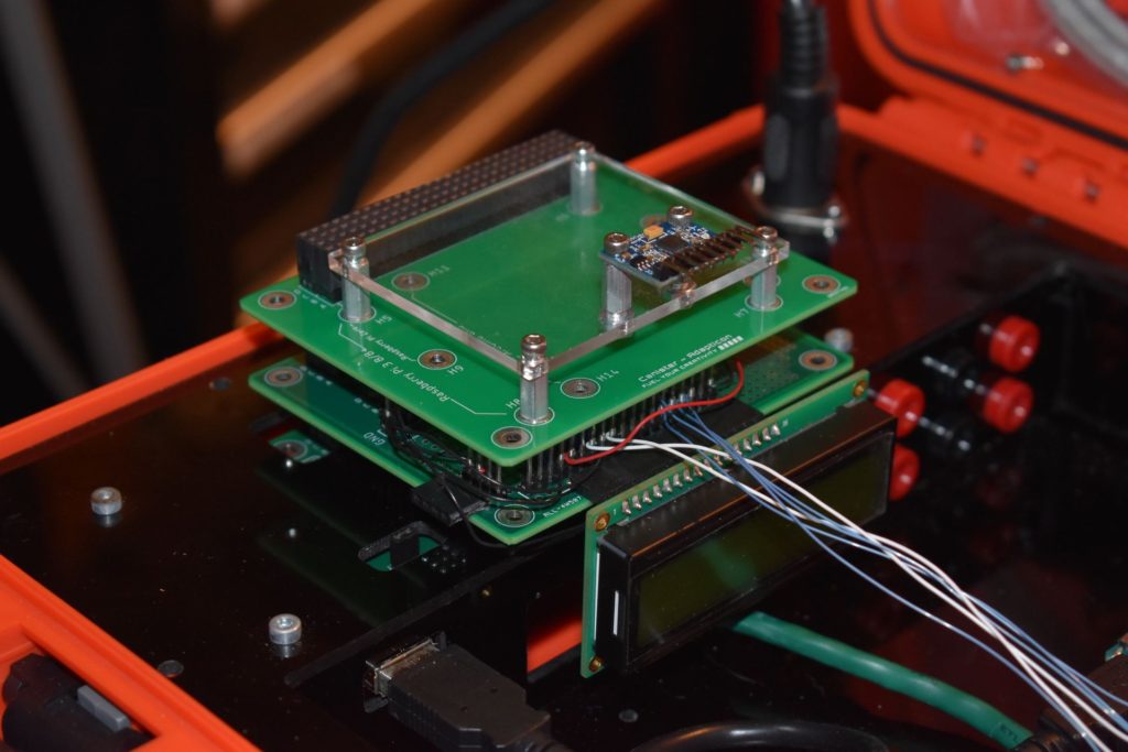
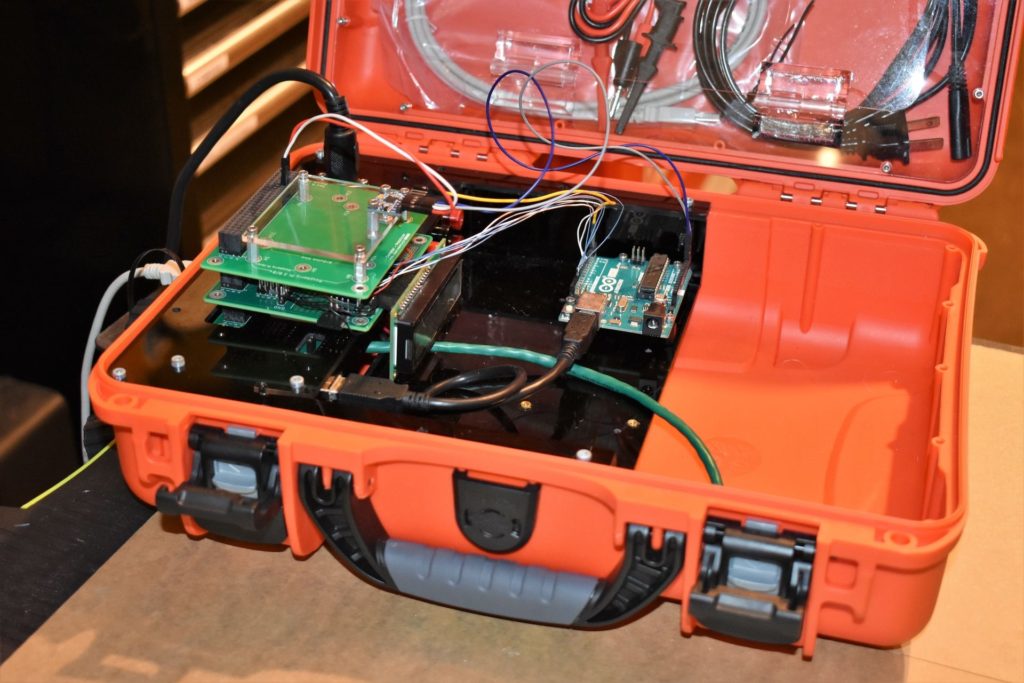
An image of the FuelCan integrated with the MPU6050 and Arduino Uno is shown below.
For additional information about the Fuelcan-910, click here.
Software Overview
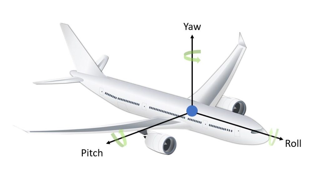
Our main goal is to grab the accelerometer data from registers 0x3B to 0x40 and the gyroscope data from registers 0x43 to 0x48 via I2C. Getting the data from each register is the easy part. The hard part is the processing and fusing of the accelerometer and gyroscope data together to get an accurate angular position. The accelerometer is susceptible to noise and small external forces while the gyroscope is susceptible to drift caused by the integration of the angular velocity to get position. The overall position is given in terms of yaw, pitch, and roll which is shown in the image below.
Acquiring the Accelerometer Data
Let’s start with one of the easy parts – obtaining the raw accelerometer data from registers 0x3B to 0x40. In the setup() function, we initialize I2C communication with Wire.begin() and the serial communication with Serial.begin() to display data on the Serial Monitor. The function resetMPU() is called to reset all internal registers of the MPU6050 to their default states by writing 0x00 to register 0x6B. If the device is not reset on power up, it will stay in sleep mode. Next, setAccelSensitivity() is called, with the range passed in as an argument. The range can be set to ±2g, ±4g, ±8g, or ±16g by setting the AFS_SEL[1:0] bits (bits 3 and 4 of register 0x1C). Once the device is configured, the program waits 10 seconds to let the MPU6050 stabilize.
In the loop() function, readAccel() is called with the divisor passed in as an argument. The divisor depends on what the range is set to and can be found in the MPU6050’s datasheet. For example, if the range is ±2g, the divisor is 16384.0. By doing this division, the raw accelerometer data is converted to g units where 1g = 9.8 m/s^2. Now we can proceed to calculate the roll and pitch angles with the following equations:
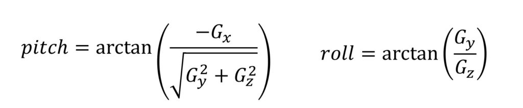
For the pitch equation, the denominator will always be positive (since both x and y components are squared), so the angles will have a range of [-90, 90]. The roll equation will have angles in the range of [-180, 180]. Since arctan could return two valid solutions, we use the atan2() function to take the quadrant into account.
I’m sure you’re wondering why we can’t just rely on the accelerometer data to obtain the object’s angular position. The first reason is that we cannot obtain the yaw measurement. Why? Consider the case when the MPU6050 is laying flat. The acceleration components will be Ax = 0, Ay = 0, Az = g. As you change the yaw angle, the reading will never change. The second reason is that the accelerometer can be noisy as it can measure all of the small external forces that are working on the object. For example, if we place an accelerometer on a drone or automobile, we would pick up the vibrations which could make the data unreliable. The third reason is that an accelerometer has a slow response time. This is where the gyroscope comes in.
Acquiring the Gyroscope Data
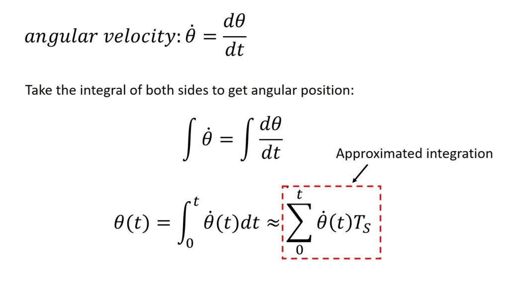
The gyroscope is not susceptible to the small external forces (i.e. vibration) and it has a fast response time, so it can be very precise. However, it suffers from drift. How is drift introduced into the system? Since the gyroscope data has units of angular velocity (rate of change of the angular position over time), we have to integrate that to get the angular position. In a digital system, this integration is approximated by taking the sum of a finite number of samples taken at a constant time interval. The equations are shown below. When noise is introduced into the system, it gets integrated as well. Also, when the gyroscope is in a static position (not moving), the output of the gyroscope is not constant. As a result, this causes the output to drift.
In the example below, we acquire the raw data from registers 0x43 to 0x48. As we mentioned previously, we have to convert the raw data to having units of degrees. First, we have to divide the raw data by a constant depending on what the sensitivity range was set to. For this example, the range was set to ±250 dps (degrees per second), so we have to divide by 131 per the datasheet. This division gives us the gyroscope data in degrees/second.
The time interval is obtained between two successive reads of the gyroscope data. This is used to calculate the approximated integration. Once the time interval is known, we multiply the interval by the current gyroscope data and add it to the previous gyroscope data.
If you decide to upload the code below, you will see the effects of drift, as the data grows to infinity. To fix this problem, we have to fuse the accelerometer and gyroscope data.
Accelerometer and Gyroscope Data Fusion
There are two popular methods to fuse the accelerometer and gyroscope data together. The first and more complex method is to use the Kalman filter. This filter is powerful, but it can be very challenging to implement on an embedded system. The second and easier method is the Complementary filter. This filter leverages both the sensors’ advantages to overcome their disadvantages.
When the accelerometer and gyroscope data are acquired, the dataFusion() function is called to fuse the data together with the Complementary filter. The equations to calculate the pitch and roll are shown below:
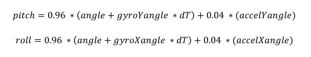
The gyroscope and accelerometer data constantly updates based on the sampling frequency, dT. On each iteration, 96% of the current value is added to 4% of the angle calculated by the accelerometer. When you upload this code, the pitch and roll no longer drift. However, the yaw still drifts since we cannot implement the Complementary filter on this angle. This led to chip manufacturers putting a magnetometer on the same chip as the accelerometer and gyroscope. So, instead of having 6 degrees of freedom, you would now have 9 degrees of freedom, and you would be able to get rid of the yaw drift. If you are interested in such a device, the MPU9150 has all three sensors.
Eliminating Yaw Drift
Another way to remove the yaw drift is to use the MPU6050’s Digital Motion Processor (DMP). There is not much documentation on how to use the DMP, but Jeff Rowberg created an excellent library that uses the DMP. The link to his GitHub repository can be clicked via the button below.
The DMP is able to perform the complex calculations onboard that are required to obtain the object’s angular position. It is able to calculate the output in both quaternions and Euler angles.
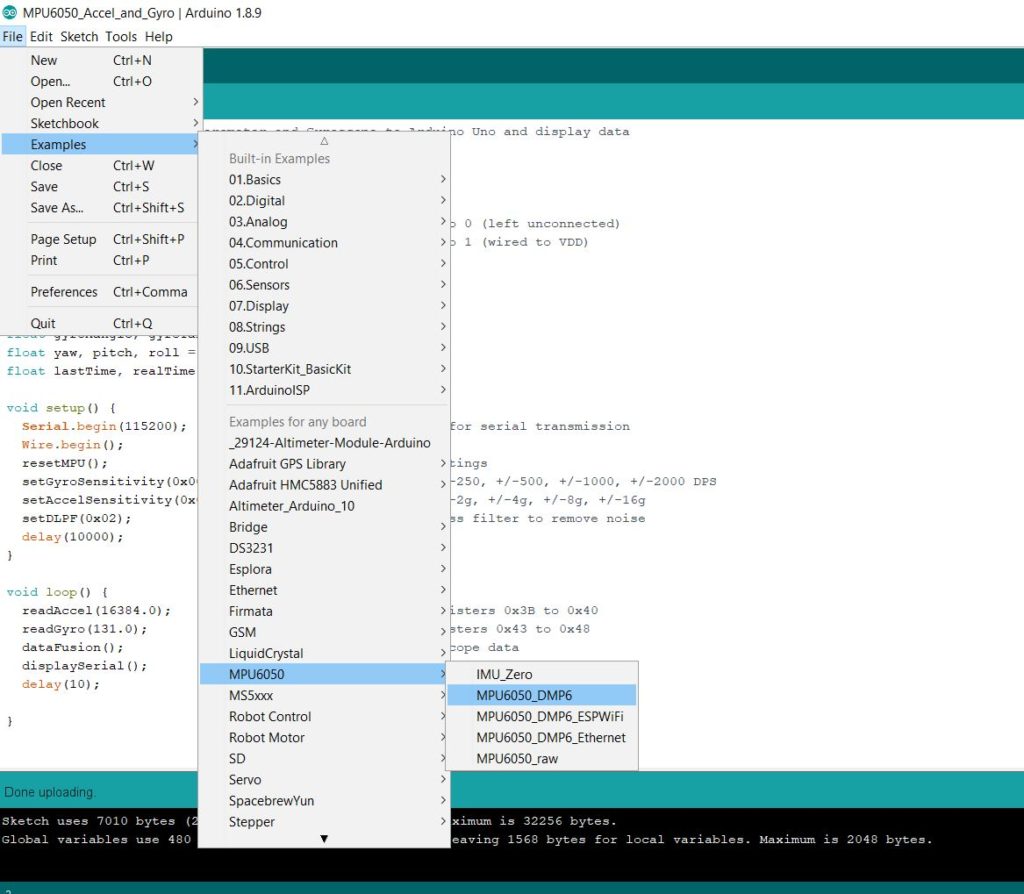
Once you install the library, open up the example MPU6050_DMP6, as shown in the image below. Upload the code to your Uno and watch as the drift is eliminated for yaw, pitch, and roll!
About Author
Eric Shea is the founder of ProteShea and is an electrical engineer. He wishes to have a major impact on bridging the gap between engineering theory and real-world applications. He has worked at Kratos Defense, SpaceX, Air Force Research Laboratory, and Polaris Industries. He received a M.S. in electrical engineering from the University of Pittsburgh and a B.S. in electrical engineering from the University of Florida.
setDLPF() is not defined! Did you leave it out? Please help.
Chris – it was never defined, so I removed the call to the function. You don’t necessarily need to enable the low pass filter unless you’re putting the MPU6050 on, say, a drone, to measure its direction/orientation. The vibration that couples to the chassis could kill the accuracy of the measurement, if you don’t have the filter enabled.