Welcome to ProteShea – in this project, we’re going to show you how to interface an anemometer to the Arduino Uno for acquiring wind speed. We’ll describe the operating principles behind how an anemometer works, hardware setup, and software to get your own system running. You don’t have to depend on those unreliable weather apps that are recording wind speeds for your entire city in one location.
Excuse the pun, but this project will be a breeze!
Disclaimer
ProteShea, LLC is a participant in the Amazon Services LLC Associates Program, an affiliate advertising program designed to provide a means for sites to earn advertising fees by advertising and linking to Amazon.com
Some links may be affiliate links, in which ProteShea, LLC earns a commission if you use that affiliate link. Please note that this is at no additional cost to you and helps us in creating more content.
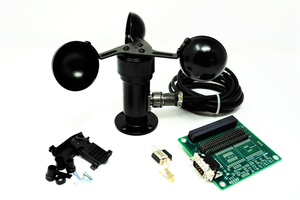
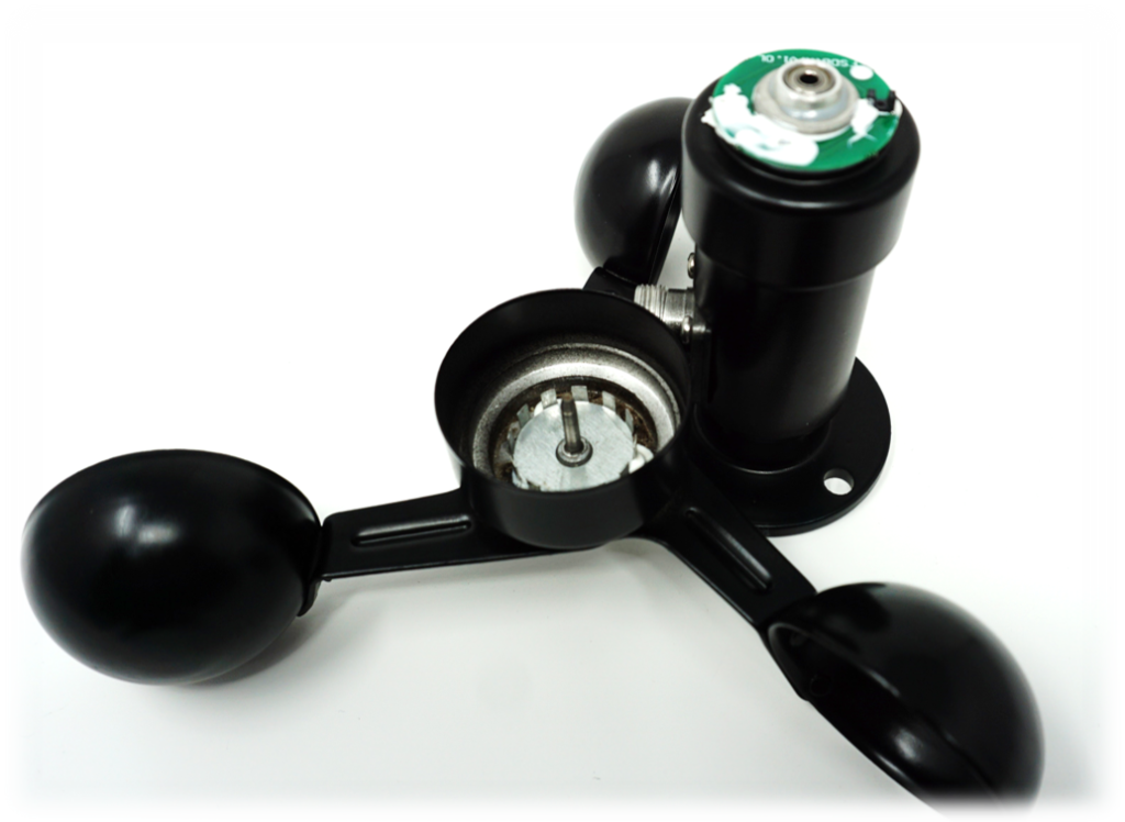
Cup anemometers use the basics of rotational velocity for measuring wind speed, but many flavors of anemometers exist including thermal, vane, ultrasonic, and hot wire. We’ll focus on the theory behind the operation of a cup anemometer, as shown in Fig. 1. Figure 2 shows the disassembled anemometer (NOTE: disassembling will damage sensor), revealing the gear tooth mechanism and vane reed switch.
Fig. 1. Cup Anemometer Integration with VersaSMT Canister
Fig. 2. Gear Tooth Mechanism and Vane Reed Switch
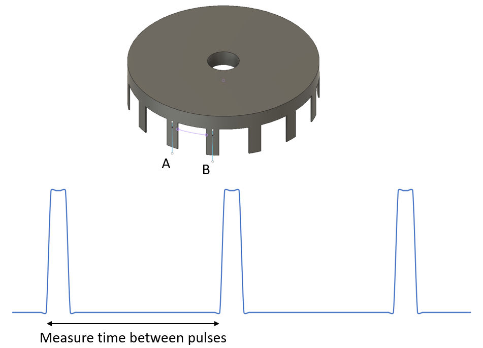
Animation 1. Pulses from Vane Reed Switch
When the cups spin, a magnet or a gear-tooth mechanism passes by or between a hall effect sensor or reed switch. Both the hall effect sensor and reed switch depend on the existence of a magnetic field close by. As illustrated in the animation above, the gear-tooth passes through a vane reed switch and generates a square wave. A microcontroller can then measure the time between each pulse (A to B) in Fig. 3 to determine the wind speed which is similar to what we showed in Project 12 for measuring time-of-flight for an ultrasonic sensor. For example, say our microcontroller measures the time between two pulses to be 200 uSec and the distance between A and B is 6.5mm. We can then correlate this to wind speed: 6.5mm/200uSec = ~30 m/s which is the maximum wind speed for this sensor.
Fig. 3. Relationship Between Distance (A to B) and Time
Since the output of this particular anemometer is an analog voltage from 0 to 5V, we suspect that a frequency to voltage converter IC is being used (i.e. analog tachometer such as the LM2907 from Texas Instruments).
Configuring the Hardware
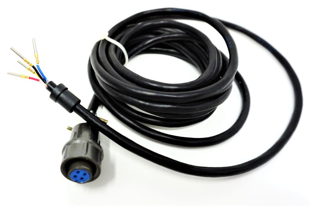
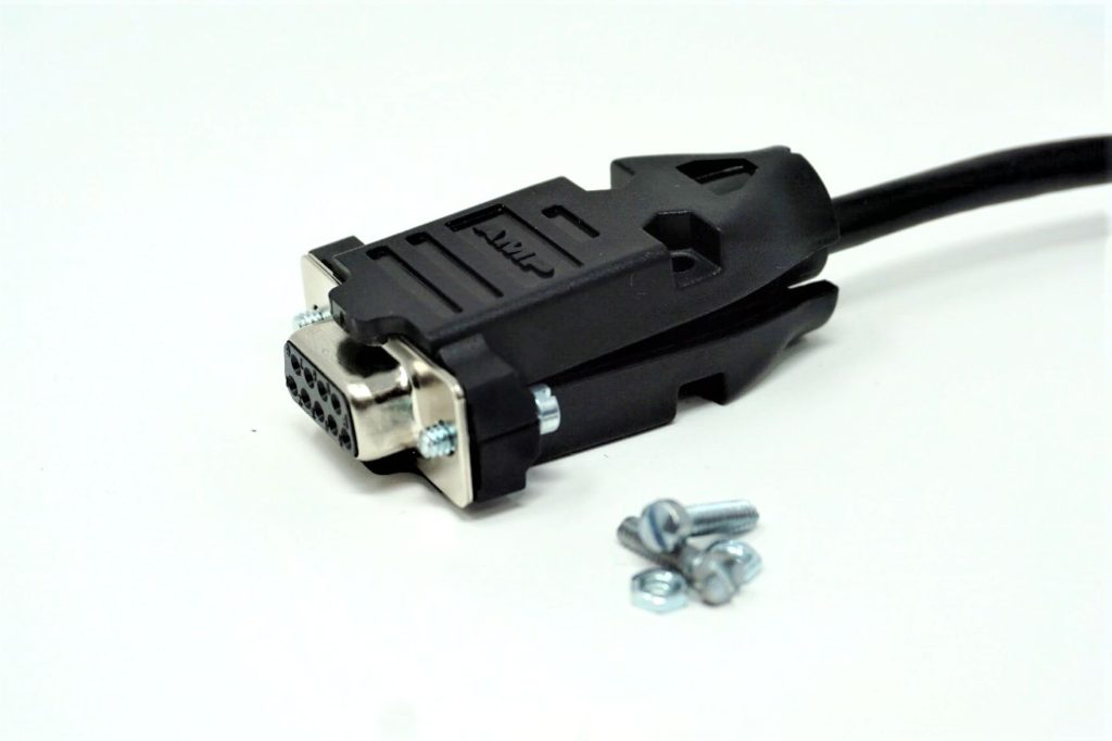
First, we’ll start with preparing the cable to connect to VersaSMT via a DB9 connector. Cut the cable to your desired length. Slide the connector boot over the bundle of wire and then strip 1/4″ of insulation away from the wire and crimp a connector socket to each wire using the D-SUB crimper tool, as shown in Fig. 4. If you forget the connector boot, you might have to start over!
Fig. 4. Preparing Cable for DB9 Connector
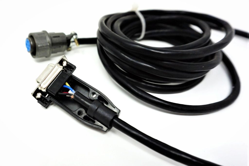
We’ll need to insert each of the connector sockets into the DB9 connector using the wiring diagram in Fig. 5 (looking at the front face of the connector). You can use an insertion tool to push the sockets all the way in, or once you have the sockets inserted as far as you can, simply use a paper clip or mini screwdriver to push them in the remaining bit until you hear a click. The finished step is shown in Fig. 6. Also, notice how the boot fits snuggly into the bottom half of the backshell.
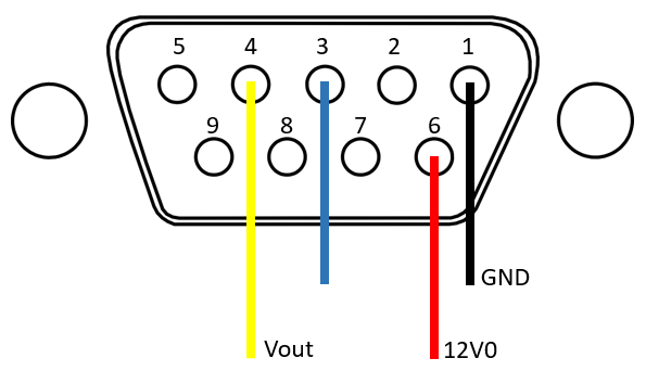
Fig. 5. DB9 Pinout
Fig. 6. Sockets Inserted into DB9 Connector
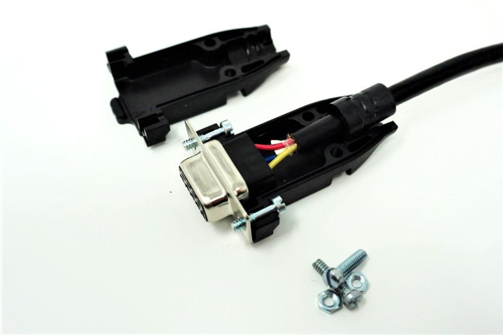
This next part is a little tricky – securing the top half of the backshell to the bottom while keeping the jack screws from falling out. Before securing the top half, place the jack screws in the connector as shown in Fig. 7. Next, align the top half over the bottom half and secure with the provided bolts/nuts, like in Fig. 8. Maybe that’s what DB should stand for in DB-9 — (D)eez (B)e slightly difficult to assemble.
Fig. 7. Placing Jack Screws
Fig. 8. Placing Top-Half of Backshell
VersaSMT Canister and Arduino Uno
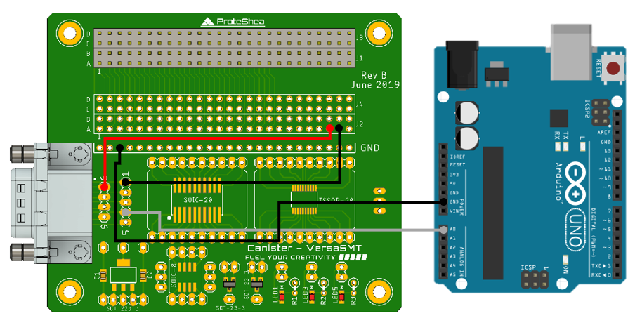
Insert VersaSMT in the FuelCan as shown in Fig. 10 and using the below diagram, we’ll now wire up VersaSMT to the Arduino. The nice feature about FuelCan is that we have an easily accessible 12V rail to power up this anemometer. We used the serial monitor in the Arduino IDE to display wind speed but feel free to use Modulus with the LCD screen for displaying your acquired wind speeds like we did in Arduino Project 9.
Fig. 9. VersaSMT to Arduino Uno WIring
FuelCan Setup
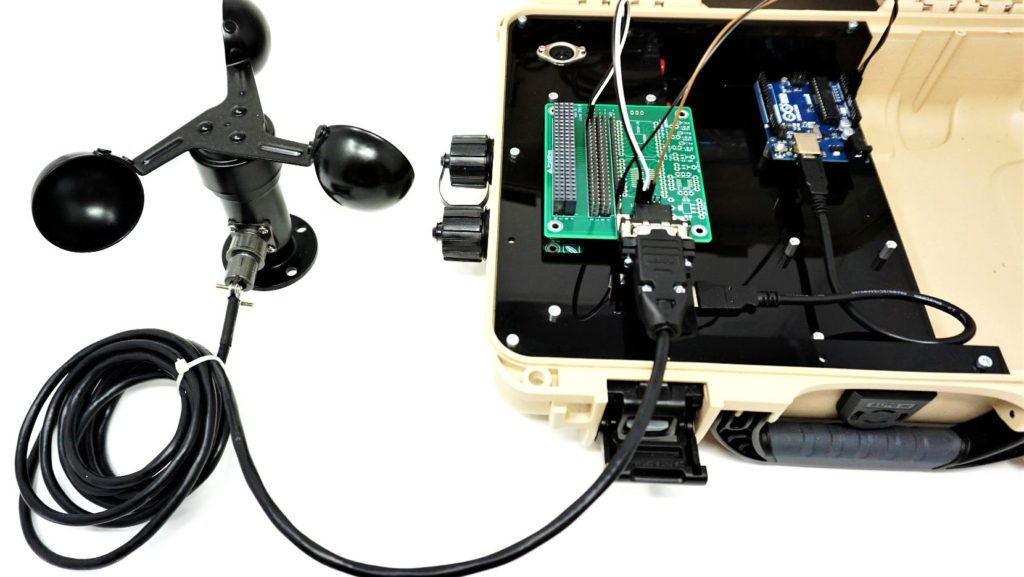
If you haven’t mounted the Uno onto the prototyping area of the FuelCan, go ahead and do that. Plug the Type A side of the USB cable into USB1 receptacle and the Type B side into the Uno’s receptacle. Power up the FuelCan with the AC-DC power adapter. The finished design with the anemometer and Arduino Uno is shown below. Now that’s a clean-looking setup!
Fig. 10. Completed Integration
Software
Once the wiring is complete and the FuelCan is powered up, we can now load the sketch shown below onto the Uno. Sensor data is read from the Arduino’s internal ADC and then converted to a voltage. In this case, the voltage is linearly proportional to the wind speed so we simply multiply by 6 to convert voltage to wind speed. The voltage and wind speed are then printed to the serial terminal.
References and Further Reading
[1] Omega.nl. 2020. Anemometer. [online] Available at: <https://www.omega.nl/prodinfo/anemometers.html> [Accessed 11 April 2020].
[2] Kjmagnetics.com. 2020. Reed Switches And Hall Effect Sensors. [online] Available at: <https://www.kjmagnetics.com/blog.asp?p=reed-switches-and-hall-effect-sensors> [Accessed 11 April 2020].
About Bradley Shea
He is the co-founder of ProteShea, believer in exceptionally crafted maker projects, an electrical engineer, and enthusiast for simplifying rocket science like concepts so that anyone can understand them. He has worked at NASA’s Kennedy Space Center and Ball Aerospace. He received a M.S. in electrical engineering from the University of Pittsburgh and a B.S. in electrical engineering from the University of Florida.
We use cookies to ensure that we give you the best experience on our website. If you continue to use this site, we will assume that you are happy with it.