Interface a Photoresistor
Last updated May 2019
Introduction
Welcome to ProteShea – in this project, we’ll be showing you how to interface a photoresistor with the Arduino Uno (rev 3) to control a LED. The photoresistor is a type of resistor where the resistance varies with light intensity. The relationship between the resistance and light intensity is negatively proportional, meaning that as the light intensity increases, the resistance decreases. These can be used in applications such as turning street lights on at night, setting traffic controllers for low-volume traffic at night, or automatic low beams on your vehicle.
Disclaimer
ProteShea, LLC is a participant in the Amazon Services LLC Associates Program, an affiliate advertising program designed to provide a means for sites to earn advertising fees by advertising and linking to Amazon.com
Some links may be affiliate links, in which ProteShea, LLC earns a commission if you use that affiliate link. Please note that this is at no additional cost to you and helps us in creating more content.
Here’s what you’ll need to get started:
- FuelCan
- Modulus or solderless breadboard
- Modulus Kit
- VersaSMT
- Arduino Uno Rev3
- Photoresistor
- Surface-mount or through-hole LED
- Through-hole 220Ω and 10kΩ resistor
- 30 AWG wire
- 30 AWG wire wrap tool
- Soldering iron
- Solder
Photoresistor
A photoresistor or light-dependent resistor (LDR) is a type of resistor where the resistance is dependent on the light intensity. As the light intensity increases, the resistance decreases, and as the light decreases, the resistance increases. You can perform a quick test with a voltmeter to see how the resistance changes. Set your voltmeter to measure resistance and place a probe on each one of the leads of the photoresistor. Shine the beam from a flashlight or other light source directly onto the photoresistor and watch the resistance decrease. We measured about 1kΩ.
Then, slowly move the beam away from the photoresistor and watch as the resistance increases. Turn off the lights for complete darkness (hopefully your voltmeter has a backlight display so you can measure the reading) and see how high the resistance gets. We measured over 5 MΩ.
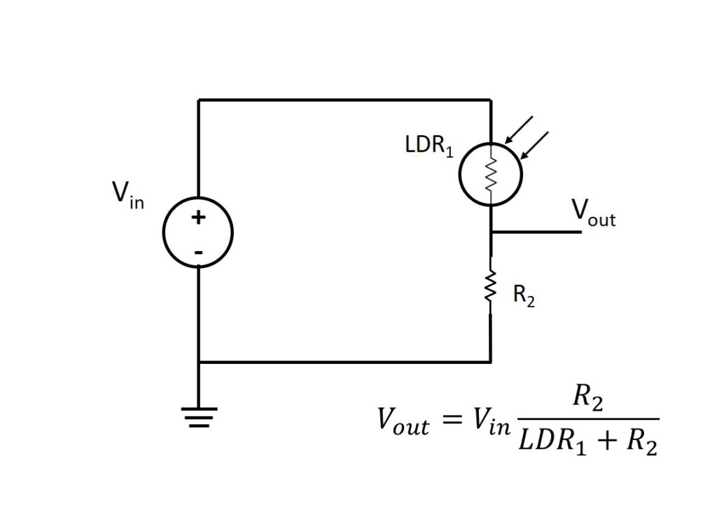
For the Uno to obtain information about the light intensity, we must place the photoresistor in a voltage divider circuit, as shown below. This will allow us to measure Vout by using the 10-bit ADC on any one of the Uno’s analog input pins (A0 – A5).
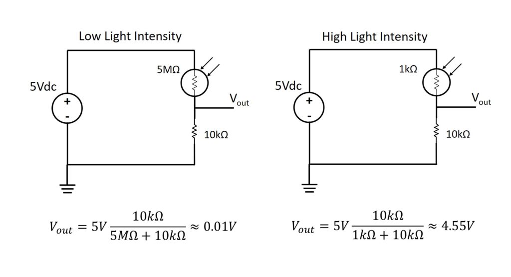
Since we measured what the resistance is for both a low and high light intensity, we can substitute these values into the voltage divider equation (shown above) to calculate Vout. Based on the calculation below, Vout increases with an increase in light intensity. This will help establish our limits in the software since we have to know when to turn on and off the LED.
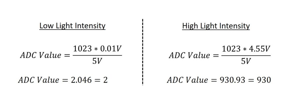
In Project 8, we showed you how to convert the voltage into an ADC value that we can use in our code. The calculations are shown below. Since we know the ADC value, we can now establish the limits that will determine if the LED will be on or off. For example, when the ADC value is greater than 90, it’s safe to say that we have a medium-to-high light condition and can therefore turn the LED off.
Connecting the Photoresistor to Modulus
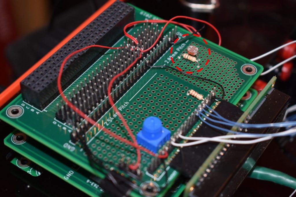
If you are not using Modulus, then you can skip to the Breadboard section. We will be soldering the photoresistor and 10kΩ through hole resistor to the 2.00mm section of Modulus. You can solder it to the 2.54mm section if you have room. Insert the photoresistor and solder the leads. Next, place the 10kΩ resistor next to the photoresistor, as circled in red in the image below, and solder the leads.
NOTE: The LCD wiring is left over from the previous projects. We are not using the LCD in this project, but it will be used in future projects.
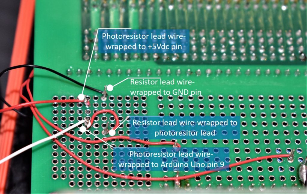
Once the photoresistor and 10kΩ resistor are soldered on, cut the leads, but make sure you leave enough of it so you can wire wrap 30AWG wire to each one. One lead of the photoresistor gets wire-wrapped to +5Vdc on the 4×26-pin breakout and the other lead gets wire-wrapped to the closest lead of the 10kΩ resistor. The other lead of the 10kΩ resistor gets wire-wrapped to a GND pin on the 4×26-pin breakout. An image is shown below with the wire-wrapping complete.
Soldering LED to VersaSMT
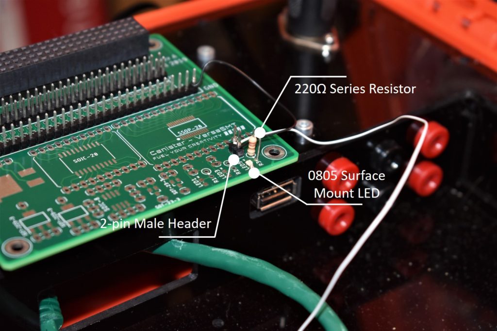
The VersaSMT Canister has three 0805 footprints where you can solder on surface-mount LEDs. There are also through hole footprints so you can solder on a series resistor to limit the current to the LED, and a 2-pin male header so you can wire-wrap.
Orient the LED so that the cathode is closest to the edge of the board and solder it on. Next, solder on the resistor and 2-pin male header, as shown in the image below. Wire wrap the male header pin closest to the LED to Uno pin 9, and the other male header pin to the GND vector.
NOTE: If the LED was oriented incorrectly, swap the wire wrap on the male header pins. This will make the header pin that is closest to the LED the GND pin and the other pin will get connected to Uno pin 9.
Canister Stack
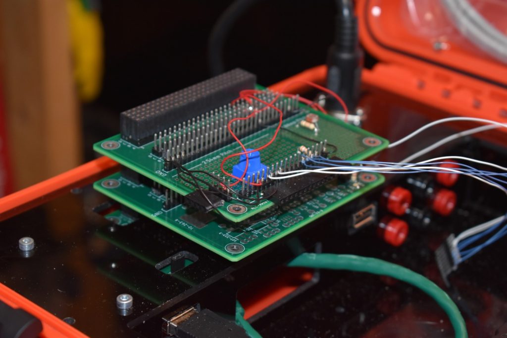
When all of the components are soldered to Modulus and VersaSMT, carefully mate the two Canisters together to create the stack. Modulus should be on top of VersaSMT. Then, insert the stack into the FuelCan’s 4×26-pin female header. An image is shown below with the stack connected to the FuelCan.
Solderless Breadboard
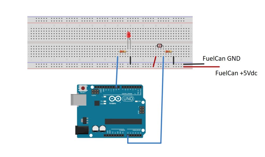
If you are using a solderless breadboard, use the schematic below to make the necessary connections.
FuelCan Wiring
If you haven’t mounted the Uno onto the prototyping area of the FuelCan, go ahead and do that. If you are using a breadboard instead of Modulus, place the breadboard in the bottom storage compartment to limit the length of the jumper wires. You’ll need to supply +5V and GND to the power and ground rails on the breadboard by using the provided banana jack to test-lead clip cables. You will need two male header pins to mount the test-lead clips on the breadboard side. Plug the Type A side of the USB cable into USB1 receptacle and the Type B side into the Uno’s receptacle. Power up the FuelCan with the AC-DC power adapter.
For additional information about the Fuelcan-910, click here.
Software
Once the wiring is complete and the FuelCan is powered up, we can now load the sketch onto the Uno. The first sketch is below. Pin 9 is set as an output, so we can drive the LED, and analog input 0 is used to obtain the output voltage from the voltage divider circuit, and convert it to a digital value. There is a single if-else statement within the loop() function – if the ADC value is greater than 90 (medium-to-high light intensity), then the LED is turned off. If the ADC value is less than or equal to 90 (low-light intensity), the LED is turned on.
The second sketch is below. Again, pin 9 is set as an output, so we can drive the LED, and analog input 0 is used to obtain the output voltage from the voltage divider circuit, and convert it to a digital value. The difference between this and the first example is that we are using a PWM signal to drive the LED. The PWM signal is dependent on the ADC value and thus, the LED brightness will vary. Since the ADC value is 10 bits and the PWM value is only 8 bits, we have to use the map() function to convert a 10-bit value into an 8-bit one. Once you load the sketch onto the Uno, wave your hand in front of the photoresistor and watch the LED vary its brightness.
About Author
Eric Shea is the founder of ProteShea and is an electrical engineer. He wishes to have a major impact on bridging the gap between engineering theory and real-world applications. He has worked at Kratos Defense, SpaceX, Air Force Research Laboratory, and Polaris Industries. He received a M.S. in electrical engineering from the University of Pittsburgh and a B.S. in electrical engineering from the University of Florida.