Interface a GPS Module
Last updated June 2019
Introduction
Welcome to ProteShea – in this project, you’ll be learning how to interface a GPS to the Arduino Uno (rev 3). Once the GPS acquires a fix from satellites, it provides you with latitude and longitude, UTC time, date, and height above sea level. This data packet is perfect for systems such as weather balloons, drones, EPIRBs (Emergency Positioning Indicating Radio Beacon), ships, and airplanes to determine their location.
Disclaimer
ProteShea, LLC is a participant in the Amazon Services LLC Associates Program, an affiliate advertising program designed to provide a means for sites to earn advertising fees by advertising and linking to Amazon.com
Some links may be affiliate links, in which ProteShea, LLC earns a commission if you use that affiliate link. Please note that this is at no additional cost to you and helps us in creating more content.
Here’s what you’ll need to get started:
20x4 Character LCD
Please see Project 10 on how to interface the 20×4 LCD in 4-bit mode. You should have pins 4, 6, and 11-14 of the LCD connected to Uno pins 2, 3, and 4-7, respectively. The LCD is mounted to the Modulus Canister via the 16-pin, right-angle female header soldered to the 1-to-1 link, as shown in the image below.
Global Positioning System (GPS)
GPS consists of a large constellation of satellites in Medium Earth Orbit (MEO) which is about 20,000 km from the earth’s surface. Each satellite travels at ~14,000 km/h (8,700 mph) and makes two orbits per day. The first GPS satellite, called Navstar 1, was launched back in February 1978 followed by many more satellites in the coming years. Since then there have been 72 GPS satellites launched.
For the constellation to work, there must be at least 24 operational satellites, even though there are 31 active satellites in orbit (for redundancy, and improved accuracy and coverage). The number and location of the satellites were chosen so that 4 – 6 satellites are in view from most places on Earth.
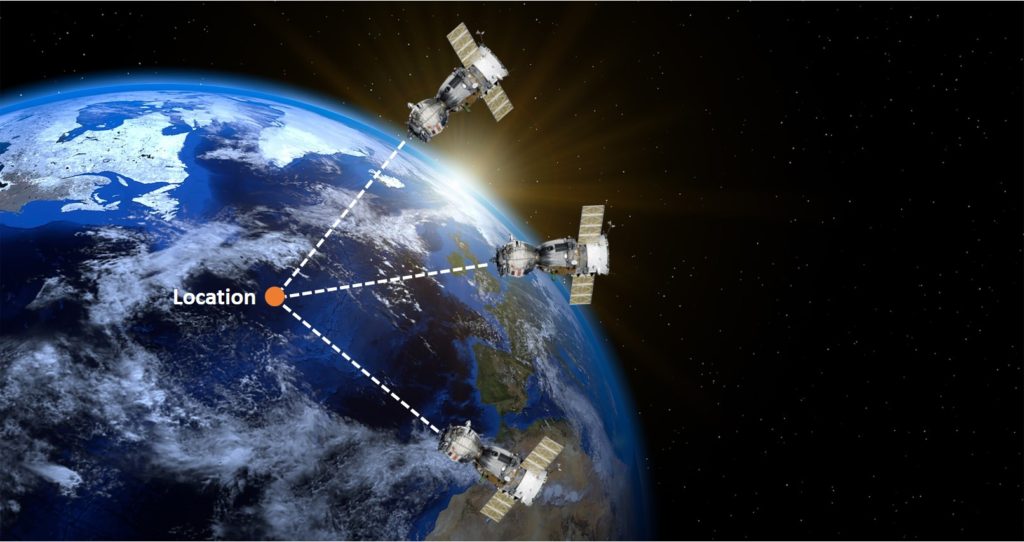
To acquire the 2D position (latitude and longitude) on Earth, a GPS receiver must receive signals from three different GPS satellites. Each satellite time stamps the exact time that each signal is sent and it also sends its exact location in orbit. When the receiver receives all three signals, it subtracts the time the signal was transmitted from the time the signal was received. Based off of these calculations, the receiver knows how far away the satellites are.
To obtain a 3D position (latitude, longitude, altitude) on Earth, a GPS receiver must receive signals from four different GPS satellites. The receiver typically tracks all of the available satellites, but it only uses data from a selection of them (chooses the satellites with higher signal strength).
A GPS satellite transmits data leveraging carriers that are in the L band which is a range of frequencies between from 1 GHz to 2 GHz on the electromagnetic spectrum. More specifically, they use bands that are centered at 1575.42 MHz (L1), 1227.60 MHz (L2), 1381.05 MHz (L3), and 1176.45 MHz (L5). The bands that are used depend on the GPS satellite. The first-generation satellites used L1 and L2 bands while modern-generation satellites can use all four bands.
The data packet transmitted from a GPS satellite contains multiple pieces of information such as the Space Vehicle Number (SVN), Pseudorandom Noise Number (PRN), and the navigation message which consists of the GPS date and time, satellite’s status, ephemeris, and almanac.
- SVN: Each satellite is uniquely identified by a serial number
- PRN: Uniquely identifies the ranging codes that the satellite uses
- Ephemeris: gives the precise location of where the satellite is in orbit
- Almanac: contains information about the status of each satellite and approximate orbital information
When a GPS receiver receives a data packet from each satellite, it formats and outputs the data using the National Marine Electronics Association (NMEA) standard. The NMEA standard is formatted in lines of data called sentences where each sentence is a comma-separated list. Each sentence begins with ‘$’, has a two-letter prefix that defines the device (i.e. ‘GP’ for GPS receivers), and a three-letter sequence that defines the contents of each sentence (i.e. GGA – fix information and RMC – recommended minimum data for GPS).
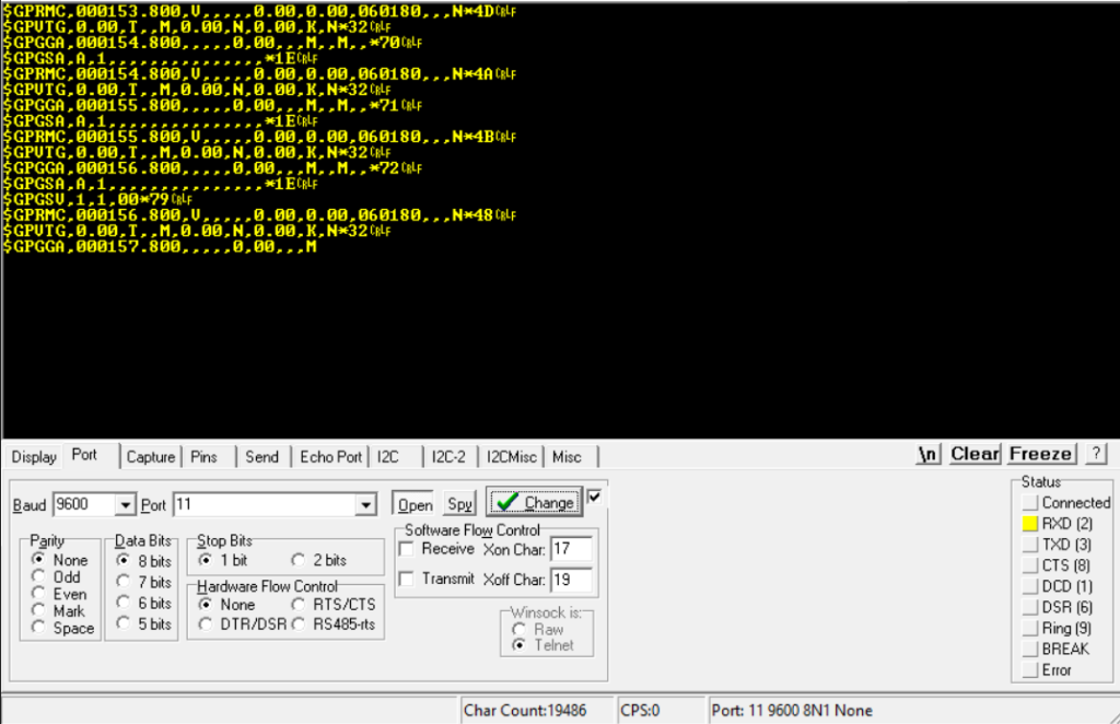
For example, in the image below, the GPS module outputs NMEA sentences with $GPRMC, $GPVTG, $GPGGA, and $GPGSA. The most common NMEA sentence types that are used are $GPRMC and $GPGGA. These two sentence identifiers contain UTC time, latitude, longitude, fix type, number of satellites acquired, and altitude.
GPS Module
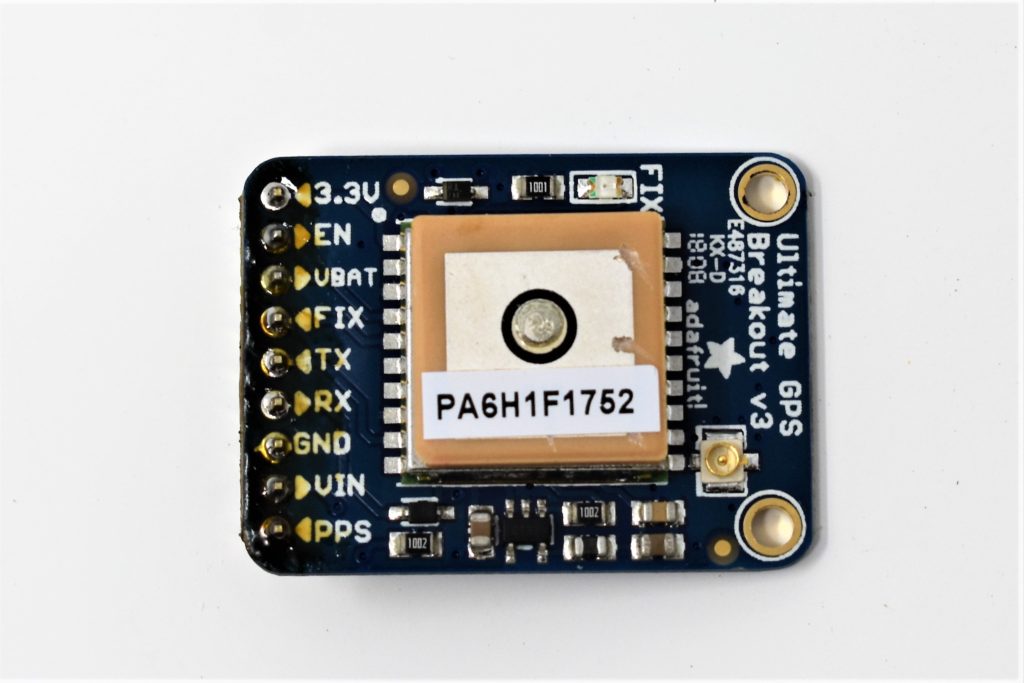
We are using the Ultimate GPS Breakout v3 from Adafruit. It has a built-in patch antenna with a sensitivity of -165 dBm. It has an update rate of 10Hz and 66 channels (each channel is used to track and search for satellites). You can also attach an external active antenna to increase the gain with the u.FL connector.
USB-UART Support Board
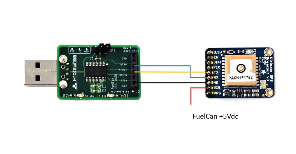
The quickest way to view the NMEA sentences sent out from the GPS module is to leverage the USB-UART Support Board which plugs into USB1 on the FuelCan. It converts the data into a USB data stream that the host can interpret and display on a serial terminal such as RealTerm. The GPS module can spit out data even when it does not have a lock with GPS satellites, so you will be able to see something on the terminal. Using 8″ M/F jumper wires, connect TX -> RX-IN, RX -> TX-OUT, GND -> GND, and VIN to the FuelCan’s +5Vdc rail, as shown in the wiring diagram below.
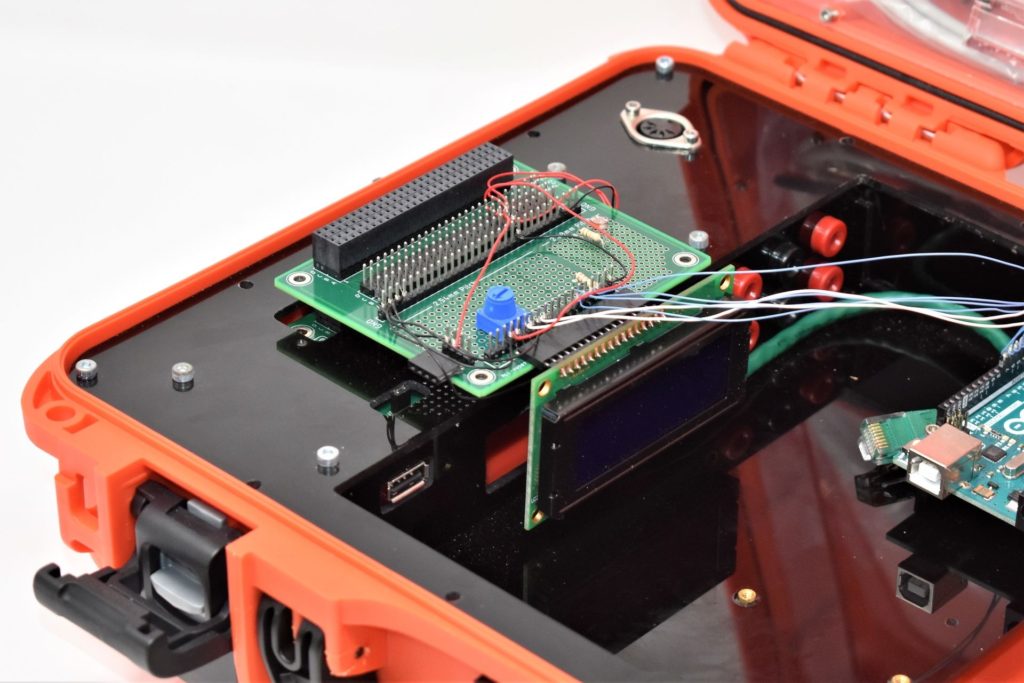
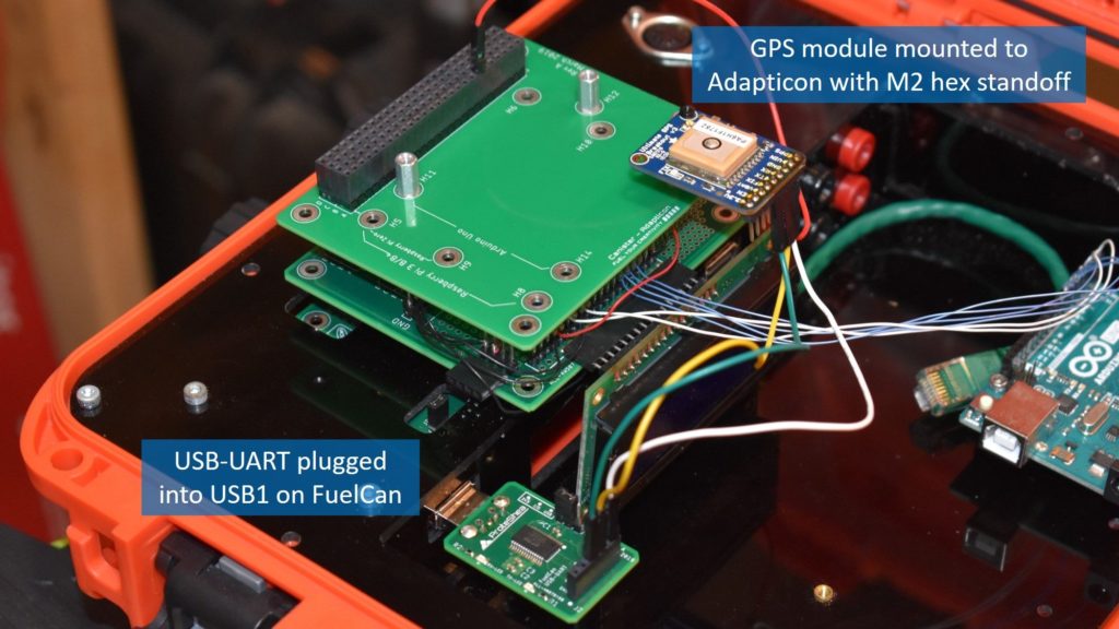
We mounted the GPS module to Adapticon with an M2 hex standoff, as shown in the image below. You can also use a solderless breadboard. Just make sure that the GPS module is pointing towards the sky and has a clear line-of-sight. If you are indoors or around tall buildings, you could have a hard time acquiring a fix.
When you power up the FuelCan with the AC-DC power adapter, you should start to see a red LED blinking once every second on the GPS module. This means that is has not acquired a fix yet, but it can still spit out data. You will also see the RX-LED blinking on the USB-UART board indicating that data is being received from the module. Open up your favorite serial terminal (we are using RealTerm) and connect to the COM port that the USB-UART board is on. Make sure that the baud rate is set to 9600 as this is the default rate of the GPS module. You should start seeing the NMEA sentences being displayed on the terminal.
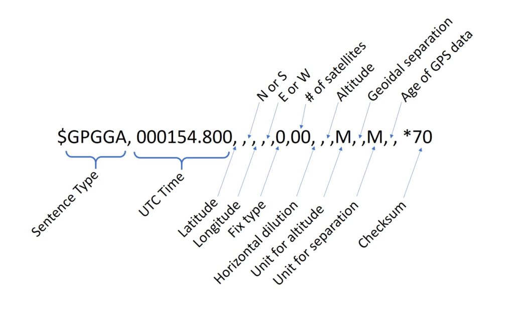
Let’s take a closer look at the $GPGGA sentence that we received in the image shown below. We have identified each part of the $GPGGA sentence. Since we do not have a fix, some fields are missing such as latitude, longitude, and altitude. You can also tell that there is not a fix by looking at the fix type which has a 0. If we had a fix, this value would be a 1.
Once the GPS module acquires a fix, you should start seeing data as shown below. The LED on the module will also start blinking once every 15 seconds. You can type in the coordinates in to the Google maps search box to confirm the accuracy of your GPS.
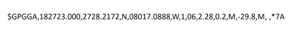
The $GPGGA NMEA sentence above contains the following information once a GPS fix is acquired:
- Time: 182723.000 is 18:27 and 23.000 seconds in UTC time
- Latitude: 2728.2172, N is 27 degrees, 28.2172 decimal minutes N
- Longitude: 08017.0888, W is 80 degrees, 17.0888 decimal minutes W
- Fix = 1 which means there is a GPS fix
- Number of Satellites: 06
- Altitude: 0.2 meters
Solderless Breadboard
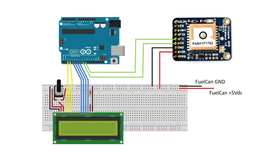
Now that we know that the GPS module works, we can wire the RX and TX pins to Uno pins 8 and 9, respectively. This is a good approach to take when integrating a new sensor or module since we limit the amount of uncertainty (i.e. if the GPS didn’t work, we wouldn’t know if it was a sensor problem or a software problem. Since we know the GPS works, the software would likely be the culprit). If you are using a solderless breadboard, use the schematic below to make the necessary connections. We are using Modulus to connect the 20×4 LCD and a solderless breadboard to connect the GPS module.
NOTE: The LCD shown is a 16×2 character display, but we are using a 20×4 character LCD. The wiring is the same.
FuelCan Wiring
If you haven’t mounted the Uno onto the prototyping area of the FuelCan, go ahead and do that. If you are using a breadboard instead of Modulus, place the breadboard in the bottom storage compartment to limit the length of the jumper wires. You’ll need to supply +5V and GND to the power and ground rails on the breadboard by using the provided banana jack to test-lead clip cables. You will need two male header pins to mount the test-lead clips on the breadboard side. Plug the Type A side of the USB cable into the USB1 receptacle and the Type B side into the Uno’s receptacle. Power up the FuelCan with the AC-DC power adapter.
For additional information about the Fuelcan-910, click here.
Software
We are leveraging Adafruit’s GPS library to parse the GPS data that is sent from the module to the Uno. It is available here. Once you download the library, uncompress it, and copy the uncompressed folder into your Libraries folder within the Arduino IDE. Restart the IDE and you should see the examples under File -> Examples -> Adafruit GPS Library.
Instead of displaying the data on the Serial Monitor, we will be displaying it on the 20×4 LCD, so we must include the LiquidCrystal.h library. Furthermore, we have to include Adafruit_GPS.h and SoftwareSerial.h libraries. Since we are using Uno pins 8 and 9 for RX and TX, respectively, we have to use SoftwareSerial to allow serial communication on these digital pins.
In the void setup() function, the LCD is configured for 20 columns and 4 rows by calling lcd.begin(20, 4), and the GPS is configured to a 9600 baud rate by calling GPS.begin(9600). Next, we command the GPS to send RMC and GGA sentence types and set the update rate to 1 Hz.
In the void loop() function, we call the function GPS.read() to grab the data from the GPS module. The function GPS.newNMEAreceived() is called to see if the most recent data received is new. If it is new, this function returns true, and then the data packet is parsed by calling GPS.parse() and passing in the argument GPS.lastNMEA().
Once the data is parsed, all we have to do is pass GPS.latitude, GPS.longitude, GPS.altitude, and GPS.speed into the lcd.print() function. Go ahead and power up the FuelCan and make sure that the Type A USB cable is plugged in so we can program the Uno. The final code is below. If the GPS has not gotten a fix, the LCD will display “Waiting for fix…” Once the GPS gets a lock, the latitude, longitude, altitude, and speed will be displayed on the LCD.
About Author
Eric Shea is the founder of ProteShea and is an electrical engineer. He wishes to have a major impact on bridging the gap between engineering theory and real-world applications. He has worked at Kratos Defense, SpaceX, Air Force Research Laboratory, and Polaris Industries. He received a M.S. in electrical engineering from the University of Pittsburgh and a B.S. in electrical engineering from the University of Florida.