Brushless DC Motor Control with ESC
Last updated June 2019
Introduction
In this project, we’ll be showing you how to control a Brushless DC Motor with an ESC and an Arduino Uno (rev 3). BLDCs are commonly found in RC cars, drones, and other aerial vehicles due to their high torque, low vibration, and high power-to-weight ratio.
The Uno reads the voltage output from a 10kΩ potentiometer with one of its analog input pins and, based on this voltage output, the Uno generates a 50Hz PWM signal with a high pulse width between 1ms and 2ms. The PWM signal is sent to the ESC which creates a corresponding 3-phase AC signal with a certain amplitude and frequency used to control the RPM of the motor.
Let’s get these motors ripping!
Disclaimer
ProteShea, LLC is a participant in the Amazon Services LLC Associates Program, an affiliate advertising program designed to provide a means for sites to earn advertising fees by advertising and linking to Amazon.com
Some links may be affiliate links, in which ProteShea, LLC earns a commission if you use that affiliate link. Please note that this is at no additional cost to you and helps us in creating more content.
Here’s what you’ll need to get started:
- FuelCan
- Solderless breadboard
- Adapticon
- Arduino Uno Rev3
- Brushless DC Motor
- 20 – 30A Electronic Speed Controller (ESC)
- XT30 Male Connector (if the ESC does not come with one)
- 2-4S LiPo battery
- Propeller (optional)
- 16×2 Character LCD
- 8″ M/M and 12″ F/M jumper wires
- 30 AWG wire
- 30 AWG wire wrap tool
- Soldering iron
- Solder
16x2 Character LCD
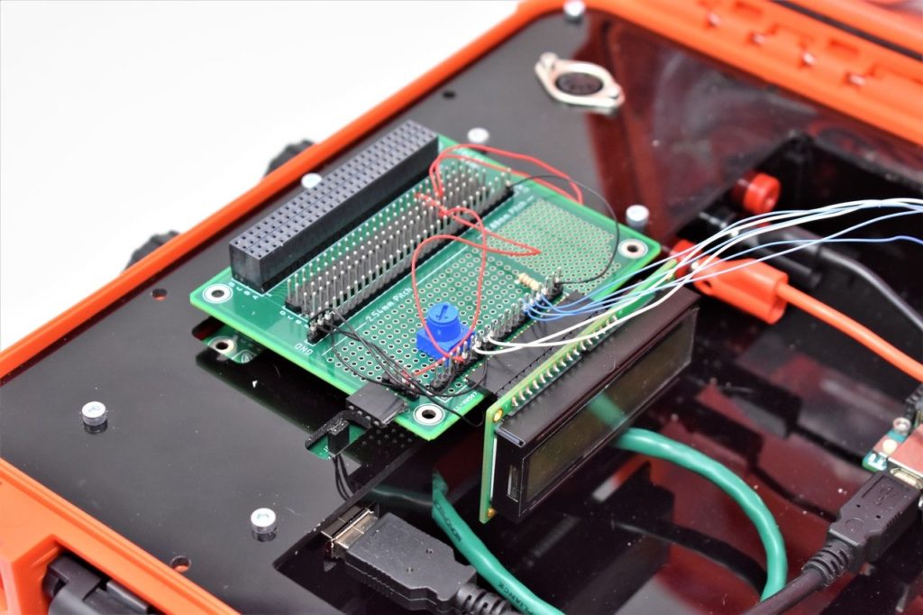
Please see Project 9 on how to interface the 16×2 LCD in 4-bit mode. You should have pins 4, 6, and 11-14 of the LCD connected to Uno pins 2, 3, and 4-7, respectively. The LCD is mounted to the Modulus Canister via the 16-pin, right-angle female header soldered to the 1-to-1 link, as shown in the image below. You can either wire wrap 30 AWG wire to connect the LCD to the Uno or use 12″ F/M jumper wires. Another option is to use a solderless breadboard to mount the LCD.
The LCD is used to display a status bar indicating the speed of the motor. This will help you keep a low speed so that you do not damage the male pins of the Canisters or the FuelCan’s 4×26-pin connector.
Brushless DC Motor (BLDC)
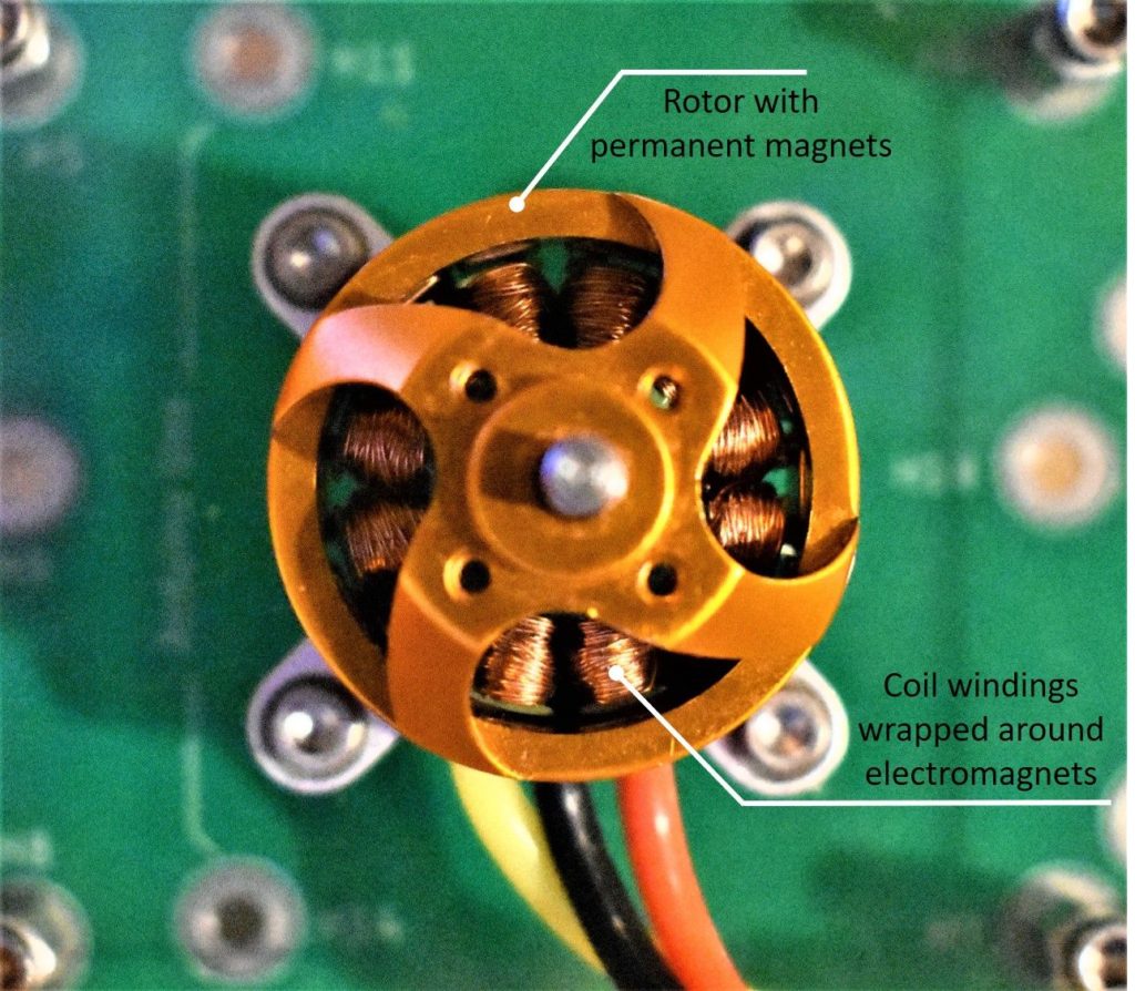
The brushless DC motor consists of permanent magnets on the outer rotor (rotating part) and electromagnets (soft metal core with insulated coil windings wrapped around it) on the inner stator (stationary part). If you look at the top of the motor, you can actually see each part, as shown in the image below.
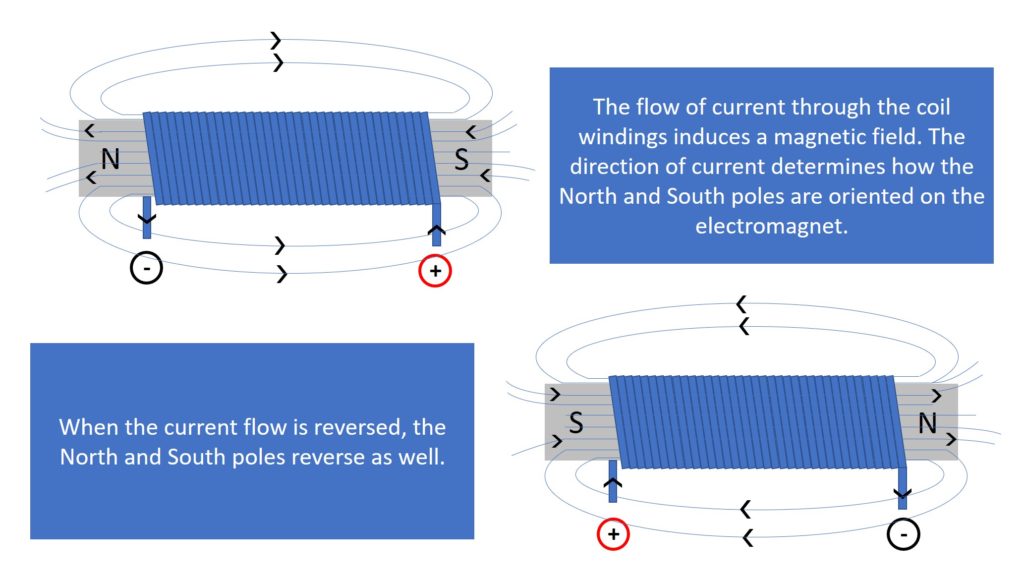
As the BLDC sits in an idle state, the electromagnets do not have a north and south pole, and thus it does not attract the permanent magnets on the rotor. To create these poles, an electric current must be sent through the coil windings. The direction of current flow determines the orientation of the poles, as shown in the image below. So, to rotate the rotor, the coils are energized and de-energized sequentially to attract the permanent magnets which causes the rotation.
When you look at the spec sheet for a BLDC, you’ll find the recommended battery voltage and KV (not to be confused with “kilovolt”) rating. For example, the BLDC we are using recommends a 2 – 4S LiPo (lithium polymer) battery and has a KV rating of 1000 (described in more detail below).
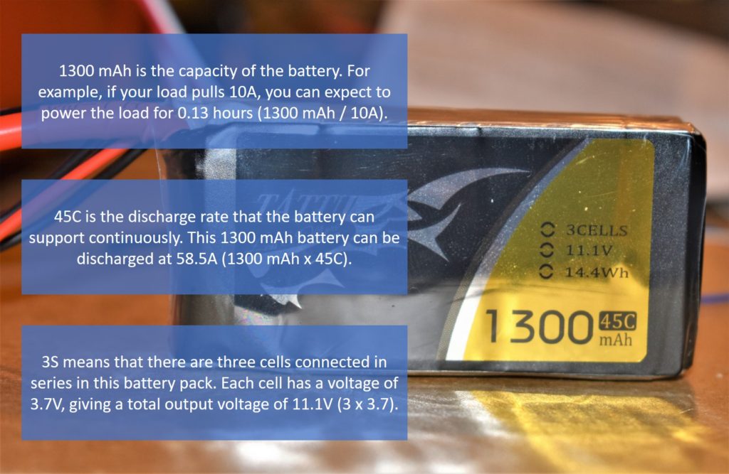
The motor is a power hungry device that requires a large amount of current in a short amount of time. This means that a high discharge rate (high C rating) is needed which LiPo batteries can supply. If you were to use a Li-ion (lithium-ion) battery, it could overheat and cause reduced battery life. We’re using a 1300mAh 45C 3S 11.1V LiPo battery. To learn what each number means, please see the image below.
Next, we have the KV rating which is the RPM (revolutions per minute) of the motor per volt with no load. For our motor, the KV rating is 1000 and since we’re using an 11.1V battery, that means we can achieve a maximum RPM of 1000KV x 11.1V = 11,100 RPM.
Okay, we know how to power the motor, but how do we control it? If we were using a brushed DC motor, all we have to do is increase the voltage for a higher RPM and decrease the voltage for a lower RPM. Controlling a BLDC is not as simple. We have to generate a 3-phase AC signal with a specific frequency and amplitude to induce a magnetic field in the coil windings to attract the permanent magnets, which causes the rotor to rotate. To do this, we use an ESC.
Electronic Speed Controller (ESC)
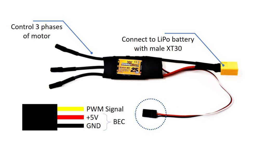
The ESC is the interface between the BLDC and the controller (Uno in this case). They consist of 3 wires on one side which connects to the BLDC, and five wires on the other side: two thicker gauge wires that connect to a LiPo battery and 3 smaller gauge wires which consists of the PWM signal and Battery Eliminator Circuit (BEC), as shown in the image below. The BEC of this ESC provides 5Vdc and up to 3A which can easily power the controller.
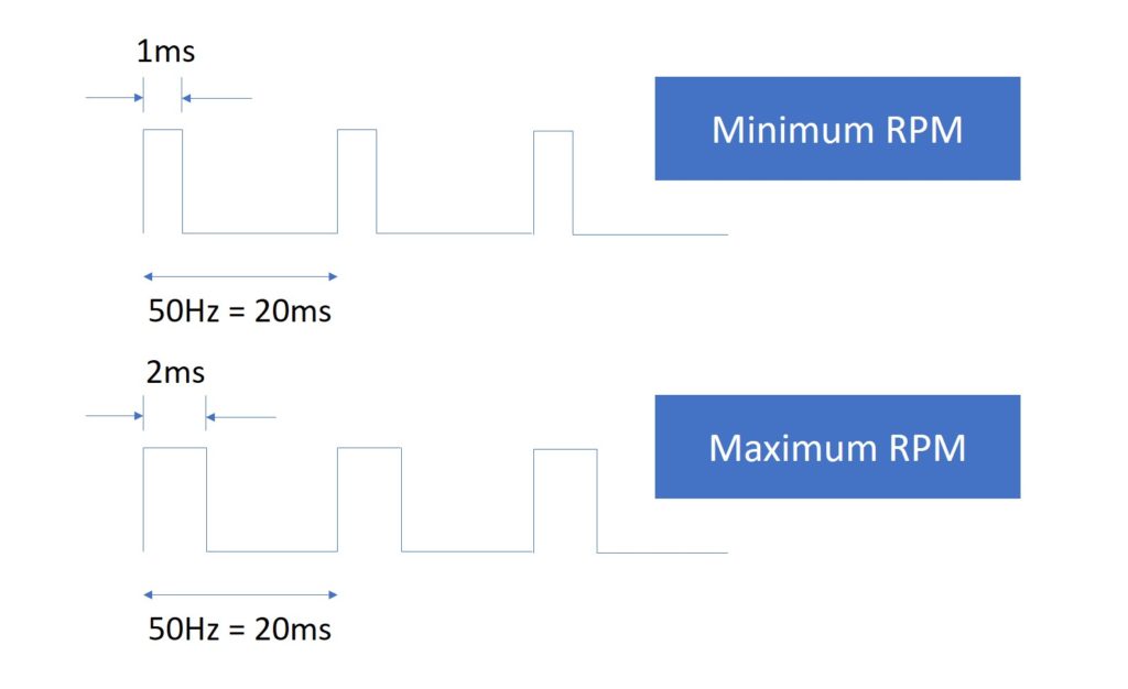
The role of the ESC is to generate the necessary signals to rotate the motor at the correct RPM. For it to generate these signals, we have to send a 50Hz PWM signal from the Uno to the ESC. The high pulse width within 1 cycle of the PWM signal must be varied between 1ms and 2ms to vary the motor’s RPM from minimum to maximum. This equates to a 5% to 10% duty cycle. An example is shown below.
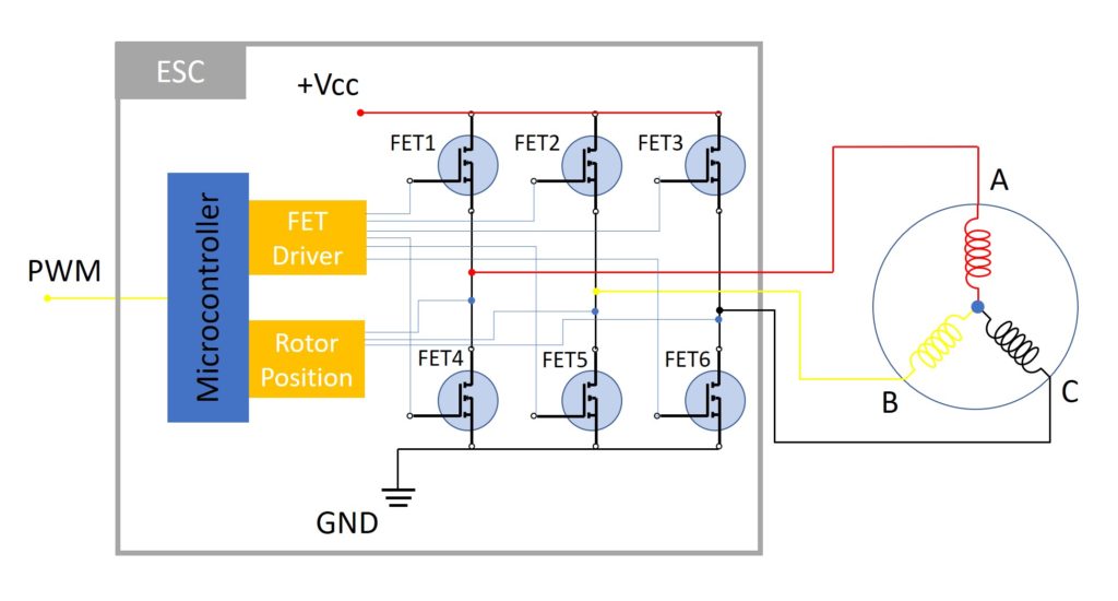
Once the PWM signal is received from the Uno, the ESC varies the switching rate of a network of FETs (Field Effect Transistors), as shown in the image below. The rate of switching causes the speed of the motor to change. There are six possible combinations of current flow: FET1 and FET6 are ON (A and C are energized), FET1 and FET5 are ON (A and B are energized), FET2 and FET4 are ON (B and A are energized), FET2 and FET6 are ON (B and C are energized), FET3 and FET4 are ON (C and A are energized), and FET3 and FET5 are ON (C and B are energized).
The next question we have to answer is how to determine the speed of the rotor to sequence the switching of the FETs. The microcontroller on the ESC measures what’s called the back-EMF which is induced on the third wire when power is being applied to the other two wires. This is caused by the magnetic field created by the permanent magnets as they rotate.
Adapticon
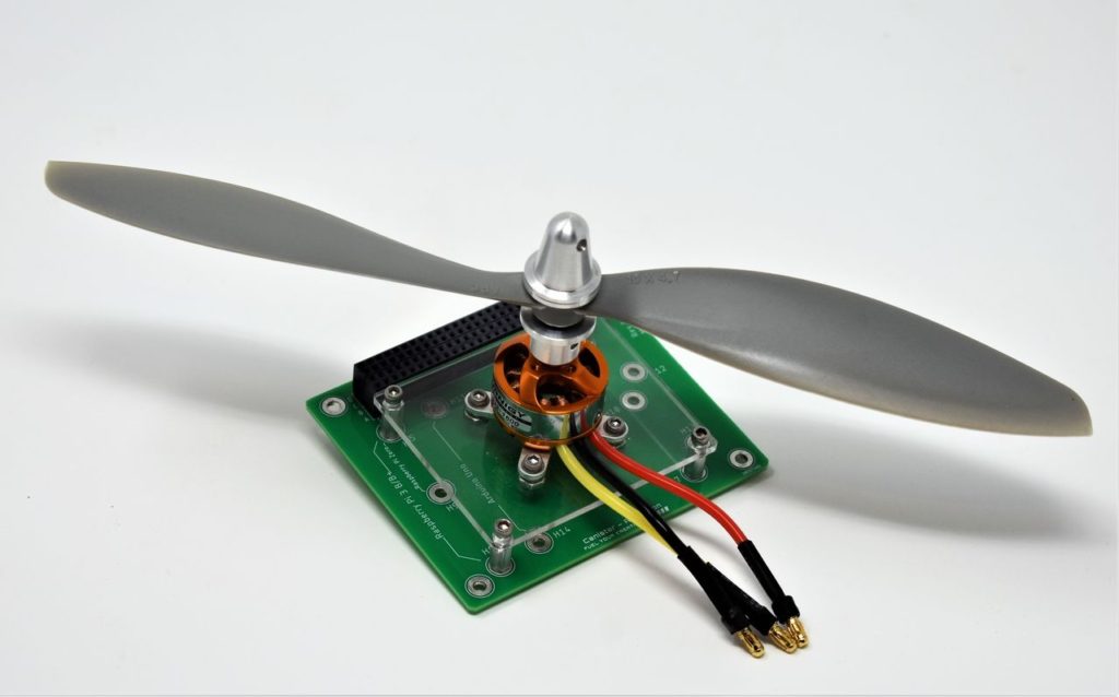
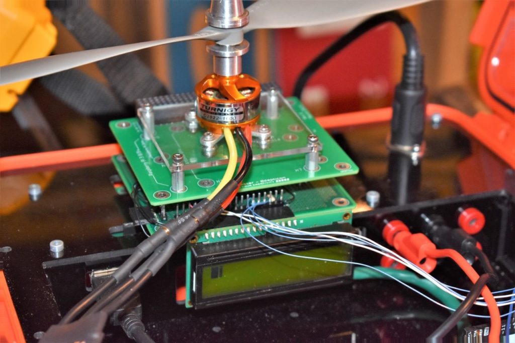
Hopefully we didn’t overload you with too much theory. It’s time to mount the BLDC to provide it a sturdy test stand. To do so, we manufactured an adapter plate made out of 1/8″ acrylic and mounted it to Adapticon with #4-40 socket head screws and #4 nuts, as shown in the image below. We recommend using lock nuts so they do not unscrew themselves from the vibration. If you are using Adapticon as a test stand, be careful not to provide too much thrust to the motor or you will damage the pins of the canister and/or the FuelCan’s 4×26-pin connector.
Click the button below to download the .step file for the adapter plate!
Once you have the BLDC mounted to Adapticon, carefully plug it into Modulus to create your Canister stack. Then, insert the stack into the FuelCan’s 4×26-pin connector, as shown in the image below.

Wiring the BLDC, ESC, and Uno
Now we can start wiring everything up. Connect the 3 phases to the BLDC – it does not matter how you connect them. You can change the connections to change the direction of rotation (if needed) once the software is uploaded to the Uno.
Connect the 3-pin female header to a solderless breadboard by using a 3-pin male header. Route the PWM signal wire (white or yellow) to pin 9 on the Uno using an 8″ M/M jumper wire and the GND wire (black or brown) to the GND pin on the Uno. We are powering the Uno with the +5V rail from the FuelCan, so we can leave the +5V wire (red) that is part of the BEC on the ESC disconnected.
Sometimes the ESC does not come with the male XT30 connector soldered on. If that is the case, solder one on and make sure that the polarity is correct (+ and – are labeled on the connector). Do not plug in the battery just yet – we will do that once the software is loaded onto the Uno.
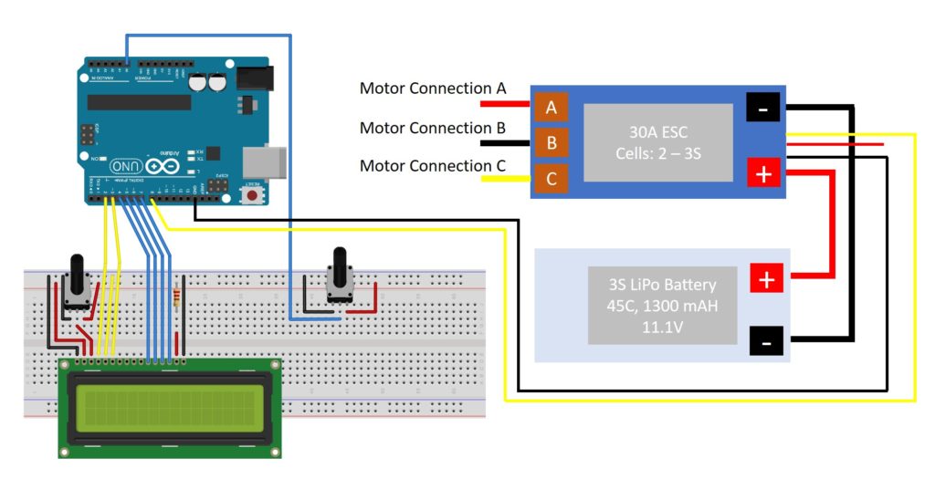
You also need to wire a 10kΩ potentiometer to vary the speed of the motor. You can either solder the potentiometer to Modulus and wire wrap to the Uno, or insert it into the breadboard and use jumper wires. Either way, connect the output of the potentiometer to Uno pin 9. The final circuit schematic is shown below.
FuelCan Wiring
If you haven’t mounted the Uno onto the prototyping area of the FuelCan, go ahead and do that. Place the breadboard in the bottom storage compartment to limit the length of the jumper wires. You’ll need to supply +5V and GND to the power and ground rails on the breadboard by using the provided banana jack to test-lead clip cables. You will need two male header pins to mount the test-lead clips on the breadboard side. This is used to power the LCD and potentiometer, and to have common ground between the FuelCan, Uno, and ESC.
Next, plug the Type A side of the USB cable into USB1 receptacle and the Type B side into the Uno’s receptacle. Plug in the 6′ Type A to Type A cable – one end into the external USB connector and the other end into the host (i.e., computer). Power up the FuelCan with the AC-DC power adapter.
For additional information about the Fuelcan-910, click here.
Software
Once the wiring is complete and the FuelCan is powered up, we can now load the sketch onto the Uno. The sketch is below. The code is similar to Project 6 and 8 where we controlled a pan-tilt module (has two servo motors) and connected a potentiometer to the analog input pins, respectively.
First, a servo object is created called ESC1 and in the setup() function, this object gets attached to pin 9 (first argument). The second and third argument passed into this function are the min and max pulse widths, respectively. We already established the fact that these are 1ms and 2ms (or 1000μs and 2000μs).
In the loop() function, the A0 analog input is read and assigned to variable A0value, which is then passed into the map() function. This function has to be used because the ADC value is 10 bits (0 to 1023), while the servo value can only be between 0 and 180. The new value returned by map() is assigned to A0value and is then passed into the ESC1.write() function.
Once the code is uploaded, you can connect the LiPo battery to the ESC. To arm/initialize the ESC, the high pulse width of the PWM signal must be less than or equal to 1ms. If the PWM signal is greater than 1ms, the motor will not spin. This is a safety factor because you don’t want the motor to spin at full throttle when you power it up.
When the high pulse width of the PWM signal is at a minimum (less than or equal to 1ms), the motor makes a beep to confirm that it is ready. You can now turn the potentiometer to vary the throttle. Again, please be careful not to throttle the motor too high or you will damage the pins on the Canister or the FuelCan’s connector. The status bar on the LCD will help you visualize where the throttle is.
ESC Calibration
You may have noticed that the motor doesn’t start to rotate as soon as you begin to turn the potentiometer. The image below shows the status bar and the motor still has yet to begin rotating. To fix this, we have to calibrate the ESC by setting new minimum and maximum points (i.e. instead of arming at 1ms, the ESC may be slightly off and needs to be calibrated to 1.1ms for its minimum high pulse width).
First, make sure that the LiPo battery is unplugged, and power up the FuelCan. Move the potentiometer to the maximum position to set the max throttle point. A “beep-beep” tone should be emitted from the motor to confirm that the max point has been set. Move the potentiometer to the minimum position to set the min throttle point. Several “beep” tones should be emitted to indicate the amount of battery cells. For example, if you have a 3S battery, you will hear three beeps. Then, you will hear a long “beep” tone which means the low point has been confirmed. You are now ready!
About Author
Eric Shea is the founder of ProteShea and is an electrical engineer. He wishes to have a major impact on bridging the gap between engineering theory and real-world applications. He has worked at Kratos Defense, SpaceX, Air Force Research Laboratory, and Polaris Industries. He received a M.S. in electrical engineering from the University of Pittsburgh and a B.S. in electrical engineering from the University of Florida.