3-Axis Magnetometer with Arduino Uno

Last updated June 2019

Introduction

Welcome to ProteShea – in this project, we’ll be interfacing the HMC5883L 3-axis magnetometer to an Arduino Uno (rev 3). This device can measure the magnitude and direction of the Earth’s magnetic field. It’s a low-power device and can be found in mobile phones or navigation systems to provide an accurate compass heading. You can also use them to detect ferrous (contains iron) metals since the iron within the metal changes the magnetic field when it’s in close proximity to the sensor.

Don’t get lost out there, let’s get started!

Disclaimer

ProteShea, LLC is a participant in the Amazon Services LLC Associates Program, an affiliate advertising program designed to provide a means for sites to earn advertising fees by advertising and linking to Amazon.com

Some links may be affiliate links, in which ProteShea, LLC earns a commission if you use that affiliate link. Please note that this is at no additional cost to you and helps us in creating more content.

20x4 Character LCD

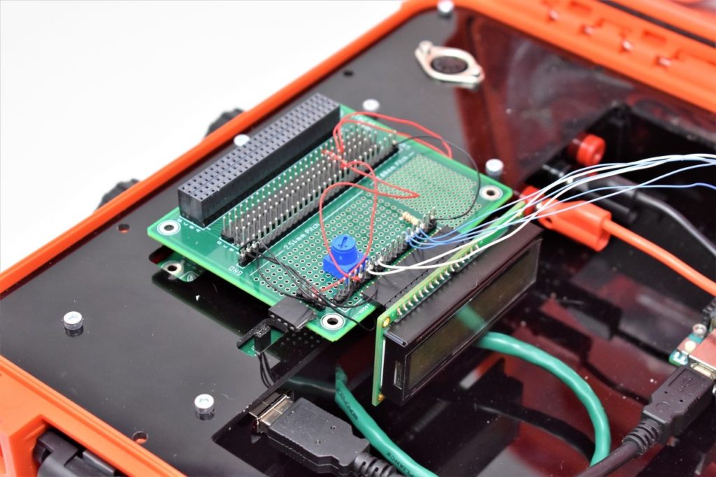
Please see Project 10 on how to interface the 20×4 LCD in 4-bit mode. You should have pins 4, 6, and 11-14 of the LCD connected to Uno pins 2, 3, and 4-7, respectively. The LCD is mounted to the Modulus Canister via the 16-pin, right-angle female header soldered to the 1-to-1 link, as shown in the image below. We recommend wire wrapping 30 AWG wire to the male header pins so you can stack Adapticon on top of Modulus. Otherwise, you can use 12″ F/M jumper wires.

Wire wrapping 30 AWG wire to male header pins to mount LCD to Modulus
16x2 LCD Mounted to Modulus

HMC5883L 3-Axis Magnetometer

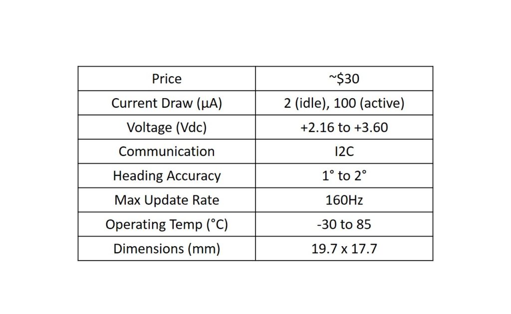
The HMC5883L 3-axis magnetometer can accurately measure the magnitude and direction of the Earth’s magnetic field in the x, y, and z direction. As a result, it can be used to provide a compass heading which is why it is also referred to as a digital compass. It is a low-powered device in a small form factor, allowing you to embed it in just about any project that requires a compass heading. A table is provided below that gives some specifications about the module.

HMC5883L Sensor Specifications

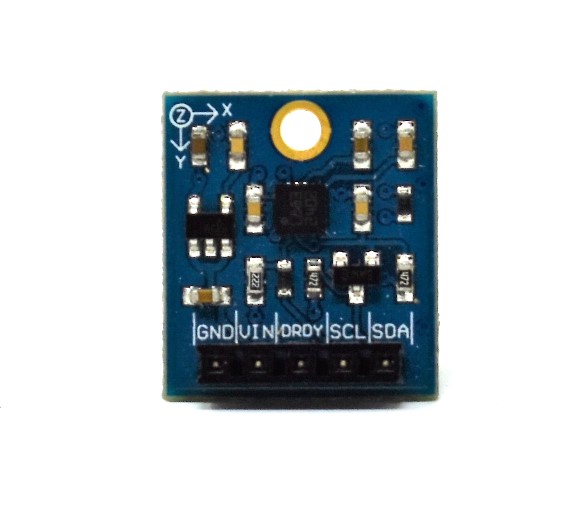
The breakout board from Although the datasheet for the HMC5883L IC consists of 5 pins: GND, VIN, DRDY, SCL, and SDA (image shown below). The GND and VIN pins are used to power the device. Although Parallax’s datasheet says that the module can operate from  2.7V to 6.5V, we had trouble getting the magnetometer to work at 5V and thus, we recommend using 3.3Vdc. The GND and VIN pins will connect to GND and 3.3V pins on the Uno, respectively.

To communicate with the device, we use the I2C protocol which only uses two pins, SCL and SDA. We use this to configure the registers on the device (i.e., setting the measurement mode and output rate), and acquire the X, Y, and Z magnetic field measurements. The device can only be 7-bit addressed at 0x1E, so you cannot have more than one of these devices on the I2C bus at one time. The SCL and SDA pins will connect to the Uno analog pins A5 and A4, respectively.

The DRDY (data ready) pin is used to tell the master device (Uno) that data is ready in the X, Y, and Z registers. The maximum output rate is 75Hz, but by using the DRDY pin, you can achieve up to 160Hz. You can connect this pin to an interrupt pin on the Uno for an efficient way to obtain the data. However, we will not be using this DRDY pin in this project.

Front view of HMC5883L breakout board
Pinout of HMC5883L Breakout Board

This device has a magneto-resistive sensor on each of its 3 axes to measure the magnetic fields. In the presence of a magnetic field, the resistance of these elements changes which causes a change in voltage across the outputs. This change in voltage is measured on each axis by the device’s 12-bit ADC and then the measurement is written to the corresponding X, Y, and Z 8-bit data registers. 

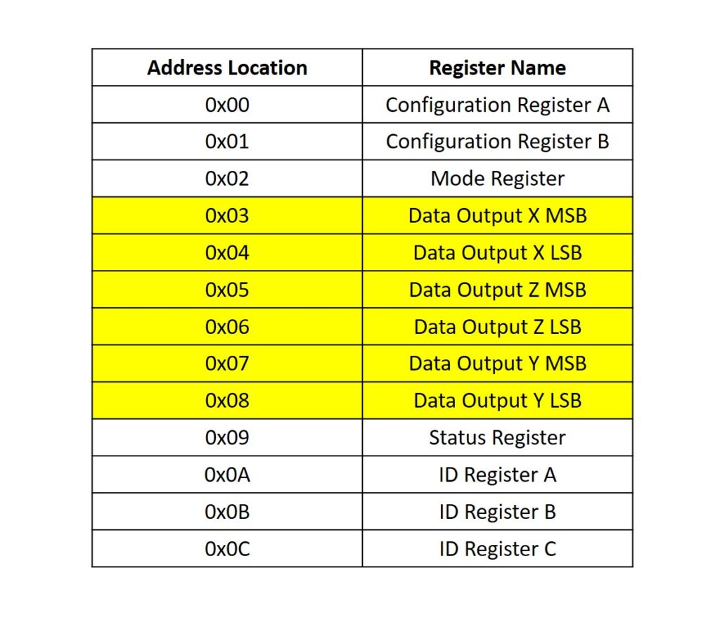
An address map of each register is shown in the table below. The registers highlighted in yellow indicate the register we will be reading from to obtain the measurements of the magnetic field on each axis. To learn more about the details of each register, please consult the datasheet for the HMC5883L IC.

Address Map for HMC5883L Registers

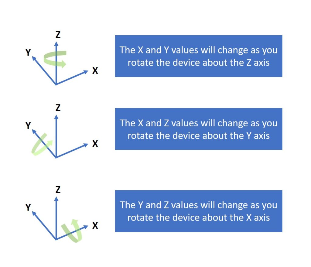
As you rotate the device about the X, Y, and Z axes, the magnetic field of each axis will change, as shown in the image below. The device must be oriented so that the X-Y plane (top plane of the board) is parallel to the ground, and also pointing upwards. 

Rotating the HMC5883L about the X, Y, and Z axes
Rotating the Device About the X, Y, and Z Axes

Mounting the Magnetometer to Adapticon

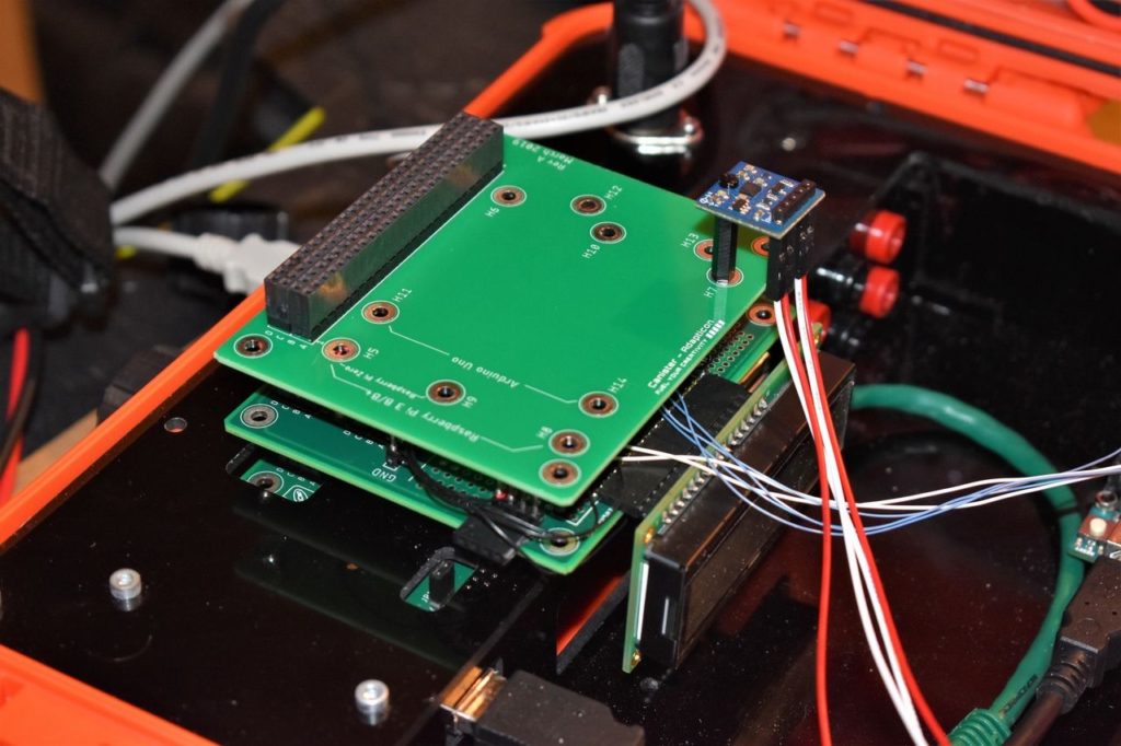
You could mount the magnetometer to Adapticon to provide stabilization. You will need an M2 male-to-female hex standoff, M2 nut, and an M2 screw to mount it. This keeps the X-Y plane parallel to the ground and allows you to rotate the FuelCan about the Z-axis, so you can get accurate compass headings. Make sure to use non-ferrous mounting hardware to avoid interference with the magnetic field. An image of the magnetometer mounted to Adapticon is shown below.

We just left the device attached to the 12″ jumper wires so we can freely move it around in all directions.

magnetometer mounted to adapticon canister with nylon M2 hardware
Magnetometer Mounted to Adapticon with Nylon Hardware

Solderless Breadboard

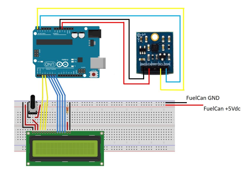
If you are using a solderless breadboard, use the schematic below to make the necessary connections for the 16×2 LCD. The magnetometer connects directly to the Uno with 12″ F/M jumper wires. We are using the 3V3 supply from the Uno instead of the 3V3 rail of the FuelCan since the 0.1″ pitch of the male header pins is too close to mount the test-lead clip cables next to each other.

NOTE: The schematic shows a 16×2 character LCD, but the 20×4 LCD is pin compatible. The only change you have to make is in the software. 

Breadboard Circuit Schematic

FuelCan Wiring

If you haven’t mounted the Uno onto the prototyping area of the FuelCan, go ahead and do that. If you are using a breadboard instead of Modulus, place the breadboard in the bottom storage compartment to limit the length of the jumper wires. You’ll need to supply +5V and GND to the power and ground rails on the breadboard by using the provided banana jack to test-lead clip cables. You will need two male header pins to mount the test-lead clips on the breadboard side. This is used to power the LCD. 

Next, plug the Type A side of the USB cable into USB1 receptacle and the Type B side into the Uno’s receptacle. Plug in the 6′ Type A to Type A cable – one end into the external USB connector and the other end into the host (i.e., computer). Power up the FuelCan with the AC-DC power adapter.

For additional information about the Fuelcan-910, click here.

Software Explanation

We communicate with the device via I2C, so be sure to include the Wire.h library. Before we can start acquiring data from the device, we first have to configure it using functions setOperatingMode() and setSamples() to set the operating mode to continuous and set the number of samples averaged per measurement output to 8. Everything else will be left as default. 

Now that the registers are configured, we can start acquiring the raw X, Y, and Z data with the function getXYZ(). This function grabs each of the 16-bit data for X, Y, and Z. The Wire.requestFrom() function within getXYZ() is used to request the 6 bytes of data.

Once we have the raw X, Y, and Z values, the function convert() is called to convert the raw count to Gauss (unit used to measure magnetic field). To make the conversion, we must consult Table 9 (Gain Settings) of the IC’s datasheet. Since the Gain was left as default, we are using a gain of 1090. We can simply divide each raw count by the gain to convert the count into units of Gauss.

The last thing to do before we output the data to the Serial Monitor is to calculate the heading. If the device is oriented with the X-Y plane parallel to the ground, we can use the X and Y values to obtain the vector that indicates the heading. This is done with the function getHeading(). The arctangent is calculated between the (X, Y) point and the x-axis, as shown in the image below. The reason we use atan2 is to be able to calculate the arctangent in all four quadrants.

Calculating the Compass Heading

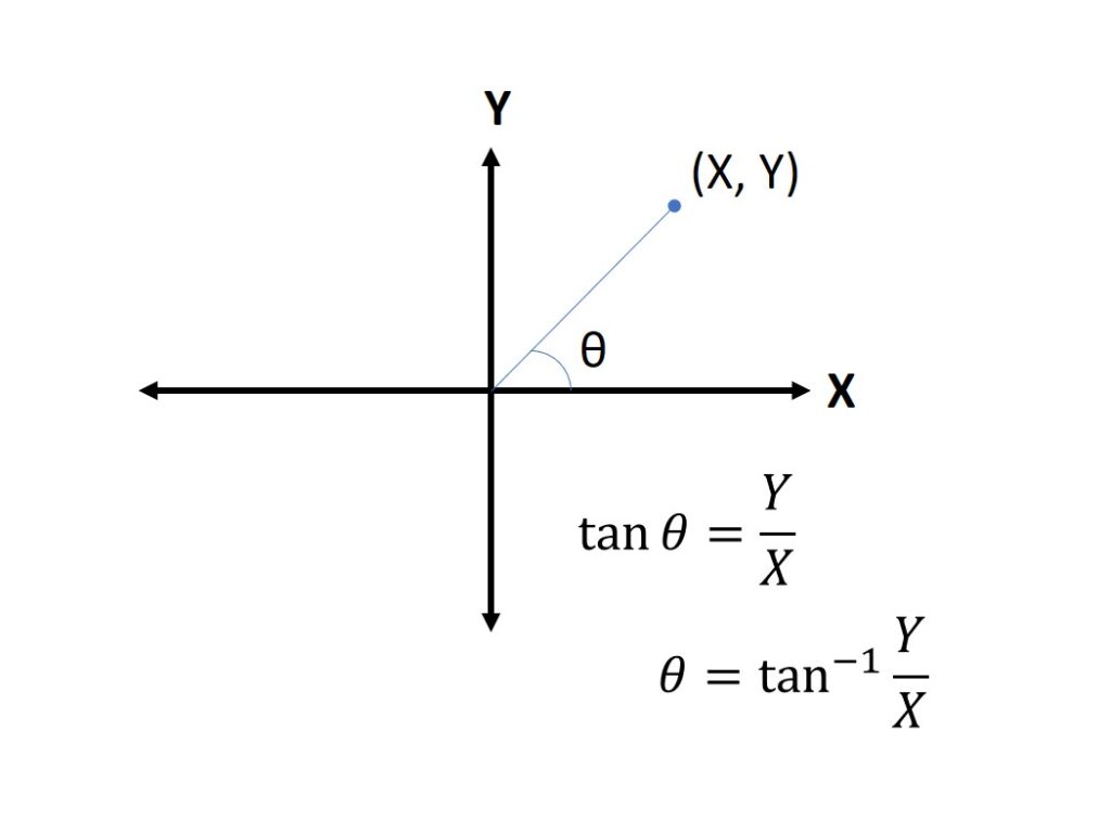
atan2 returns the angle in radians, so we can convert this to degrees. A compass only gives a heading from 0 to 360 degrees, and if we get a heading outside of this range, we can add 360 if it is negative or subtract 360 if it is greater than 360. Now that the data has been normalized and the heading has been calculated, we can display it via the Serial Monitor.

//Interface a HMC5883L 3-axis digital compass to an Arduino Uno
/*Copyright (c) 2019, ProteShea LLC
All rights reserved.
Redistribution and use in source and binary forms, with or without
modification, are permitted provided that the following conditions are met:
1. Redistributions of source code must retain the above copyright
notice, this list of conditions and the following disclaimer.
2. Redistributions in binary form must reproduce the above copyright
notice, this list of conditions and the following disclaimer in the
documentation and/or other materials provided with the distribution.
3. Neither the name of the copyright holders nor the
names of its contributors may be used to endorse or promote products
derived from this software without specific prior written permission.
THIS SOFTWARE IS PROVIDED BY THE COPYRIGHT HOLDERS ''AS IS'' AND ANY
EXPRESS OR IMPLIED WARRANTIES, INCLUDING, BUT NOT LIMITED TO, THE IMPLIED
WARRANTIES OF MERCHANTABILITY AND FITNESS FOR A PARTICULAR PURPOSE ARE
DISCLAIMED. IN NO EVENT SHALL THE COPYRIGHT HOLDER BE LIABLE FOR ANY
DIRECT, INDIRECT, INCIDENTAL, SPECIAL, EXEMPLARY, OR CONSEQUENTIAL DAMAGES
(INCLUDING, BUT NOT LIMITED TO, PROCUREMENT OF SUBSTITUTE GOODS OR SERVICES;
LOSS OF USE, DATA, OR PROFITS; OR BUSINESS INTERRUPTION) HOWEVER CAUSED AND
ON ANY THEORY OF LIABILITY, WHETHER IN CONTRACT, STRICT LIABILITY, OR TORT
(INCLUDING NEGLIGENCE OR OTHERWISE) ARISING IN ANY WAY OUT OF THE USE OF THIS
SOFTWARE, EVEN IF ADVISED OF THE POSSIBILITY OF SUCH DAMAGE.
*/
#include <Wire.h>
//Address map for registers
#define configA 0x00
#define configB 0x01
#define mode 0x02
#define dataOutX_U 0x03
#define dataOutX_L 0x04
#define dataOutZ_L 0x05
#define dataOutZ_L 0x06
#define dataOutY_L 0x07
#define dataOutY_L 0x08
#define statusReg 0x09
//Operating modes sent to Mode register (0x02)
#define continuous 0x00
#define single 0x01
#define idle 0x02
#define i2c_addr 0x1E
#define gain 1090
int16_t x = 0;
int16_t y = 0;
int16_t z = 0;
float heading;
float gaussX;
float gaussY;
float gaussZ;
void setup() {
Wire.begin();
Serial.begin(9600);
setOperatingMode(continuous);
setSamples();
}
void loop() {
getXYZ();
convert(x,y,z);
getHeading(gaussX,gaussY,gaussZ);
Serial.print("X: ");
Serial.print(gaussX);
Serial.print(" Y: ");
Serial.print(gaussY);
Serial.print(" Z: ");
Serial.println(gaussZ);
Serial.print("Heading: ");
Serial.println(heading);
delay(500);
}
//Convert the raw X, Y, Z counts to Gauss
void convert(int16_t rawX, int16_t rawY, int16_t rawZ){
gaussX = (float)rawX/gain;
gaussY = (float)rawY/gain;
gaussZ = (float)rawZ/gain;
}
//accounts for declination (error in magnetic field which is dependent on location)
void getHeading(float X, float Y, float Z){
heading = (atan2(Y,X) - 0.1) * 180 / PI;
if (heading < 0) heading += 360;
if (heading > 360) heading -= 360;
}
void setSamples(void){
Wire.beginTransmission(i2c_addr);
Wire.write(configA); //write to config A register
Wire.write(0x70); //8 samples averaged, 15Hz output rate, normal measurement
Wire.endTransmission();
delay(10);
}
void setOperatingMode(uint8_t addr){
Wire.beginTransmission(i2c_addr);
Wire.write(mode); //write to mode register
Wire.write(addr); //set measurement mode
Wire.endTransmission();
delay(10);
}
//get the raw counts of X, Y, Z from registers 0x03 to 0x08
void getXYZ(void){
Wire.beginTransmission(i2c_addr);
Wire.write(0x03);
Wire.endTransmission();
Wire.requestFrom(i2c_addr, 6);
if (Wire.available() >= 6){
int16_t temp = Wire.read(); //read upper byte of X
x = temp << 8;
temp = Wire.read(); //read lower byte of X
x = x | temp;
temp = Wire.read(); //read upper byte of Z
z = temp << 8;
temp = Wire.read(); //read lower byte of Z
z = z | temp;
temp = Wire.read(); //read upper byte of Y
y = temp << 8;
temp = Wire.read(); //read lower byte of Y
y = y | temp;
}
}

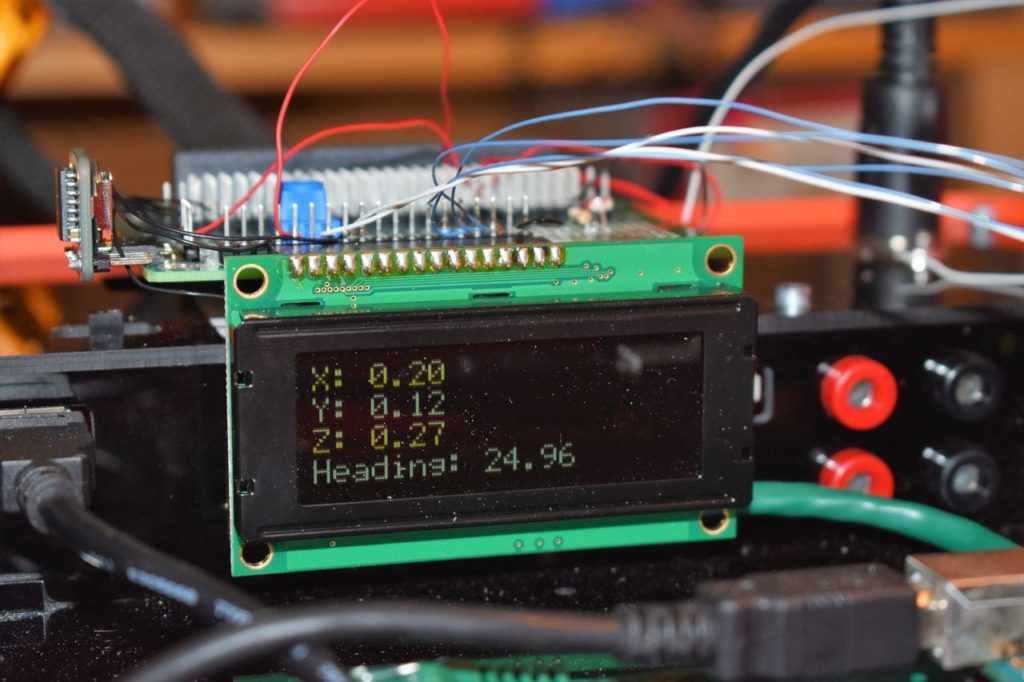
The next example displays the data on the 20×4 LCD by calling the function writeLCD().

magnetometer data being displayed on 20x4 LCD
Displaying Data on 20x4 LCD
//Interface a HMC5883L 3-axis digital compass to an Arduino Uno and display
//data on 20x4 LCD
/*Copyright (c) 2019, ProteShea LLC
All rights reserved.
Redistribution and use in source and binary forms, with or without
modification, are permitted provided that the following conditions are met:
1. Redistributions of source code must retain the above copyright
notice, this list of conditions and the following disclaimer.
2. Redistributions in binary form must reproduce the above copyright
notice, this list of conditions and the following disclaimer in the
documentation and/or other materials provided with the distribution.
3. Neither the name of the copyright holders nor the
names of its contributors may be used to endorse or promote products
derived from this software without specific prior written permission.
THIS SOFTWARE IS PROVIDED BY THE COPYRIGHT HOLDERS ''AS IS'' AND ANY
EXPRESS OR IMPLIED WARRANTIES, INCLUDING, BUT NOT LIMITED TO, THE IMPLIED
WARRANTIES OF MERCHANTABILITY AND FITNESS FOR A PARTICULAR PURPOSE ARE
DISCLAIMED. IN NO EVENT SHALL THE COPYRIGHT HOLDER BE LIABLE FOR ANY
DIRECT, INDIRECT, INCIDENTAL, SPECIAL, EXEMPLARY, OR CONSEQUENTIAL DAMAGES
(INCLUDING, BUT NOT LIMITED TO, PROCUREMENT OF SUBSTITUTE GOODS OR SERVICES;
LOSS OF USE, DATA, OR PROFITS; OR BUSINESS INTERRUPTION) HOWEVER CAUSED AND
ON ANY THEORY OF LIABILITY, WHETHER IN CONTRACT, STRICT LIABILITY, OR TORT
(INCLUDING NEGLIGENCE OR OTHERWISE) ARISING IN ANY WAY OUT OF THE USE OF THIS
SOFTWARE, EVEN IF ADVISED OF THE POSSIBILITY OF SUCH DAMAGE.
*/
#include <Wire.h>
#include <LiquidCrystal.h>
//Address map for registers
#define configA 0x00
#define configB 0x01
#define mode 0x02
#define dataOutX_U 0x03
#define dataOutX_L 0x04
#define dataOutZ_L 0x05
#define dataOutZ_L 0x06
#define dataOutY_L 0x07
#define dataOutY_L 0x08
#define statusReg 0x09
//Operating modes sent to Mode register (0x02)
#define continuous 0x00
#define single 0x01
#define idle 0x02
#define i2c_addr 0x1E
#define gain 1090
const int RS = 2, EN = 3, D4 = 4, D5 = 5, D6 = 6, D7 = 7;
LiquidCrystal lcd(RS,EN,D4,D5,D6,D7); //set Uno pins that are connected to LCD, 4-bit mode
int16_t x = 0;
int16_t y = 0;
int16_t z = 0;
float heading;
float gaussX;
float gaussY;
float gaussZ;
void setup() {
Wire.begin();
lcd.begin(20,4); //set 20 columns and 4 rows of 20x4 LCD
setOperatingMode(continuous);
setSamples();
}
void loop() {
getXYZ();
convert(x,y,z);
getHeading(gaussX,gaussY,gaussZ);
writeLCD();
delay(500);
}
void writeLCD(void){
lcd.clear();
lcd.print("X: ");
lcd.print(gaussX);
lcd.setCursor(0,1);
lcd.print("Y: ");
lcd.print(gaussY);
lcd.setCursor(0,2);
lcd.print("Z: ");
lcd.print(gaussZ);
lcd.setCursor(0,3);
lcd.print("Heading: ");
lcd.print(heading);
}
//Convert the raw X, Y, Z counts to Gauss
void convert(int16_t rawX, int16_t rawY, int16_t rawZ){
gaussX = (float)rawX/gain;
gaussY = (float)rawY/gain;
gaussZ = (float)rawZ/gain;
}
//accounts for declination (error in magnetic field which is dependent on location)
void getHeading(float X, float Y, float Z){
heading = (atan2(Y,X) - 0.1) * 180 / PI;
if (heading < 0) heading += 360;
if (heading > 360) heading -= 360;
}
void setSamples(void){
Wire.beginTransmission(i2c_addr);
Wire.write(configA); //write to config A register
Wire.write(0x70); //8 samples averaged, 15Hz output rate, normal measurement
Wire.endTransmission();
delay(10);
}
void setOperatingMode(uint8_t addr){
Wire.beginTransmission(i2c_addr);
Wire.write(mode); //write to mode register
Wire.write(addr); //set measurement mode
Wire.endTransmission();
delay(10);
}
//get the raw counts of X, Y, Z from registers 0x03 to 0x08
void getXYZ(void){
Wire.beginTransmission(i2c_addr);
Wire.write(0x03);
Wire.endTransmission();
Wire.requestFrom(i2c_addr, 6);
if (Wire.available() >= 6){
int16_t temp = Wire.read(); //read upper byte of X
x = temp << 8;
temp = Wire.read(); //read lower byte of X
x = x | temp;
temp = Wire.read(); //read upper byte of Z
z = temp << 8;
temp = Wire.read(); //read lower byte of Z
z = z | temp;
temp = Wire.read(); //read upper byte of Y
y = temp << 8;
temp = Wire.read(); //read lower byte of Y
y = y | temp;
}
}

About Author

Eric Shea is the founder of ProteShea and is an electrical engineer. He wishes to have a major impact on bridging the gap between engineering theory and real-world applications. He has worked at Kratos Defense, SpaceX, Air Force Research Laboratory, and Polaris Industries. He received a M.S. in electrical engineering from the University of Pittsburgh and a B.S. in electrical engineering from the University of Florida.

Categories
Share on facebook
Share on twitter
Share on linkedin
Share on pinterest
Share on google
0 0 votes
Article Rating
Subscribe
Notify of
guest


0 Comments
Oldest
Newest Most Voted
Inline Feedbacks
View all comments
ProteShea

Learn. Apply. Create.

290 NW Peacock Blvd #880143
Port Saint Lucie, FL 34988