Interface a DS3231 Real-Time Clock
Last updated June 2019
Introduction
Welcome to ProteShea – in this project, you’ll be learning how to interface a Real-Time Clock (RTC) to the Arduino Uno to acquire the time, date, day of the week, Unix time, and even temperature. We’ll cover three different examples where we send the data to the Serial Monitor, send the data to a 20×4 LCD, and turn on an LED on a certain day of the week. Time is running out, so let’s get started!
Disclaimer
ProteShea, LLC is a participant in the Amazon Services LLC Associates Program, an affiliate advertising program designed to provide a means for sites to earn advertising fees by advertising and linking to Amazon.com
Some links may be affiliate links, in which ProteShea, LLC earns a commission if you use that affiliate link. Please note that this is at no additional cost to you and helps us in creating more content.
Here’s what you’ll need to get started:
20x4 Character LCD
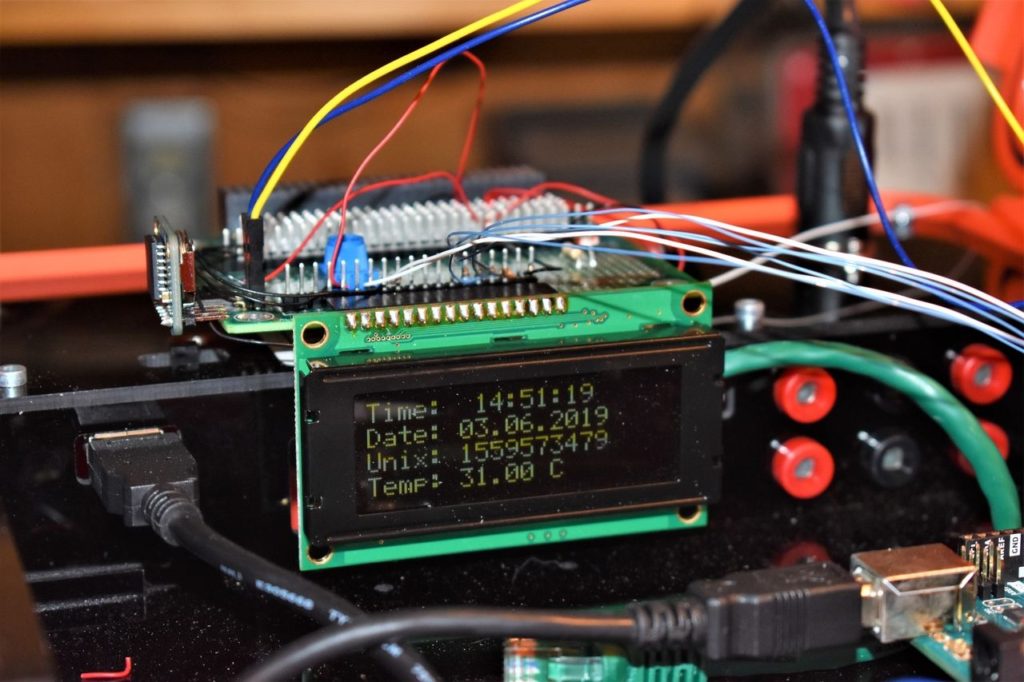
Please see Project 10 on how to interface the 20×4 LCD in 4-bit mode. You should have pins 4, 6, and 11-14 of the LCD connected to Uno pins 2, 3, and 4-7, respectively. The LCD is mounted to the Modulus Canister via the 16-pin, right-angle female header soldered to the 1-to-1 link, as shown in the image below.
DS3231 RTC
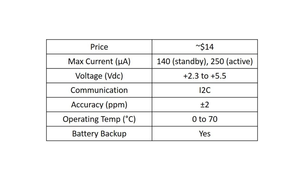
The DS3231 RTC is used to accurately provide the day of the week, date (DD/MM/YYYY), time, Unix time, and even temperature. There is a 32kHz crystal and a temperature sensor internally. The temperature sensor is used to provide feedback to the crystal since temperature effects the frequency (i.e., clock drift) of the crystal. We are using Adafruit’s DS3231 RTC breakout board which breaks out 8 pins: Vin, GND, SCL, SDA, BAT, 32k, SQW, and an active-low RST. We will only be using pins Vin, GND, SCL, and SDA. A table of specifications for the module is shown below.

There is also a battery slot to insert a CR1220 coin-cell battery which keeps track of the time and date when main power is turned off. If you don’t have this battery, you will lose this data and will have to reprogram the time and date on the DS3231 when main power is restored.
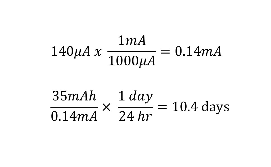
To calculate how long the battery will last, we first have to know the mAh (milliamp hours) which is the capacity of the battery. The particular cell we are using doesn’t list this, but after a quick search, the 1220 series range from about 35 – 40 mAh. The datasheet does not list how much current draw the DS3231 pulls when it is being powered from the battery, so we’ll just use its standby current draw of about 140μA. Using dimensional analysis, we can calculate the lifespan of the battery, as shown below.

The DS3231 uses the I2C protocol for communication which consists of two wires, SCL and SDA. We will be using a library created by Henning Karlsen which is available at his website: http://www.rinkydinkelectronics.com/library.php?id=73
With this library, we are able to program the initial time, and then retrieve the day of the week, data, Unix time, and temperature.
Connecting the DS3231 to Modulus
Adafruit’s DS3231 Breakout board comes with an 8-pin male header (not soldered on), but if you would like to use it with Modulus, we recommend soldering on an 8-pin right-angle male header to the DS3231.
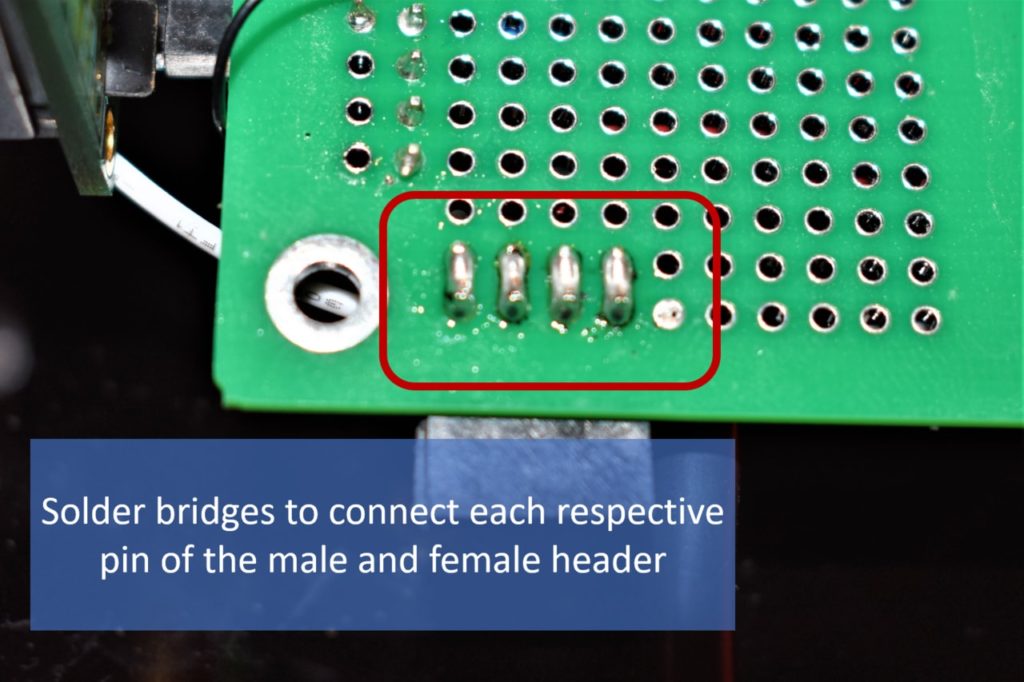
If you went through the previous projects, we only soldered on a 4-pin right-angle female header to Modulus, as shown in the image below. You can get away with this since we’re only using 4 pins on the DS3231.
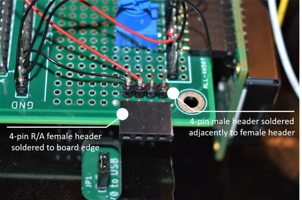


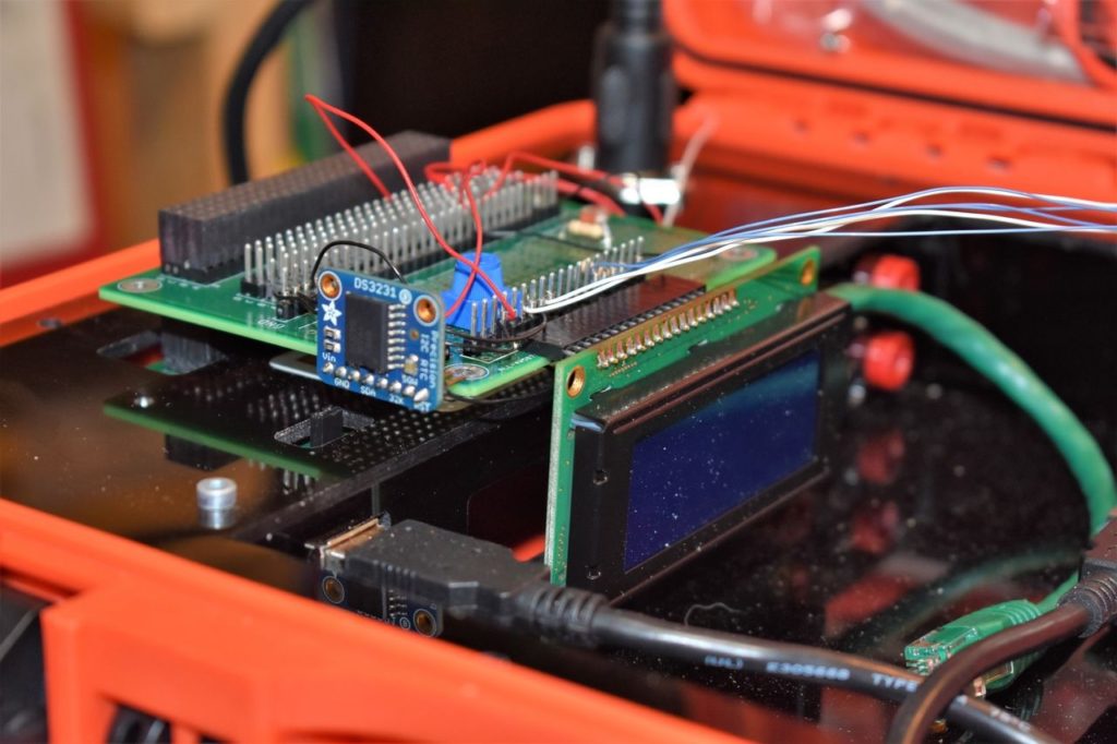
We soldered on the male header provided by Adafruit, so our DM3231 is vertically oriented, as shown in the image below. Next, we need to wire wrap Vin and GND pins to +5Vdc and GND on the Modulus Canister, and SCL and SDA to Uno pins A5 and A4, respectively. You can also use M/F jumper wires, if you prefer.

Solderless Breadboard
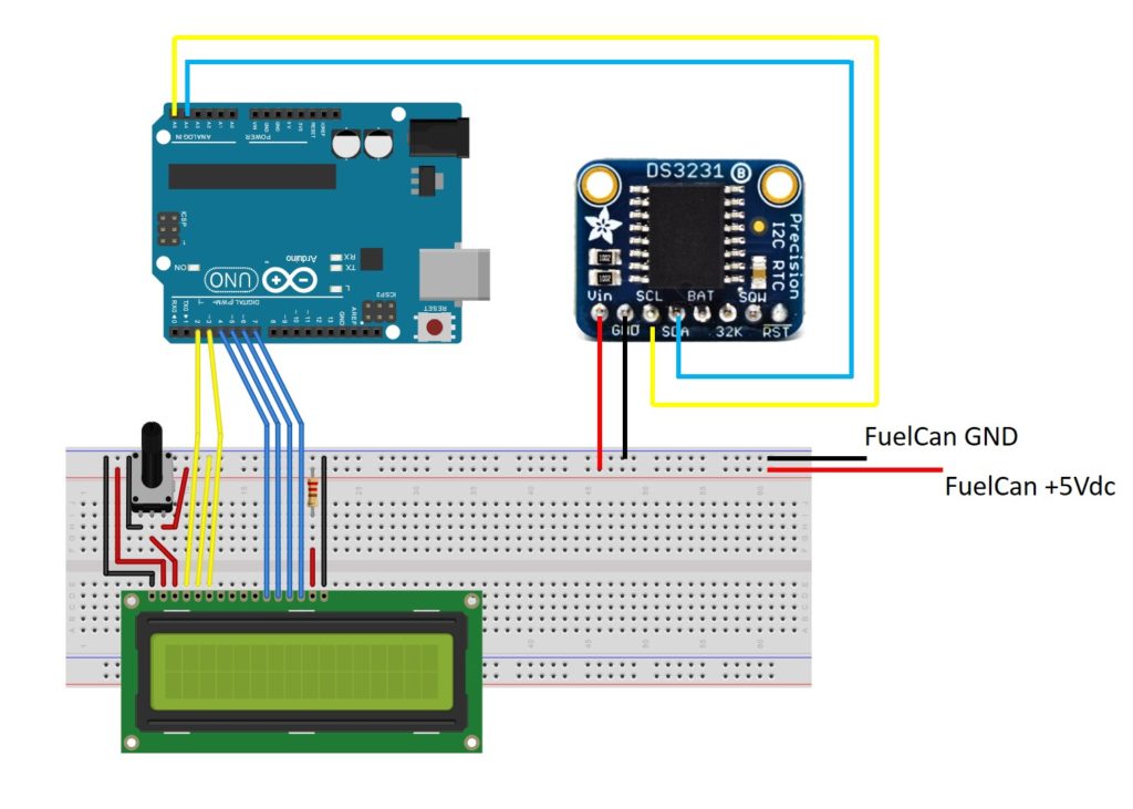
If you are using a solderless breadboard, use the schematic below to make the necessary connections to the Uno.
Twin Insight: The schematic shows a 16×2 character LCD, but the 20×4 LCD is pin compatible. The only change you have to make is in the software.

FuelCan Wiring
If you haven’t mounted the Uno onto the prototyping area of the FuelCan, go ahead and do that. If you are using a breadboard instead of Modulus, place the breadboard in the bottom storage compartment to limit the length of the jumper wires. You’ll need to supply +5V and GND to the power and ground rails on the breadboard by using the provided banana jack to test-lead clip cables. You will need two male header pins to mount the test-lead clips on the breadboard side. Plug the Type A side of the USB cable into USB1 receptacle and the Type B side into the Uno’s receptacle. Power up the FuelCan with the AC-DC power adapter.
For additional information about the Fuelcan-910, click here.
Software
Once the wiring is complete and the FuelCan is powered up, we can now load the sketch onto the Uno. The first sketch is below. To initialize the DS3231 with the date and time, we have to uncomment rtc.setDOW(), rtc.setTime(), and rtc.setDate(). Input the current time and date as arguments to their respective functions, and upload the sketch to the Uno.
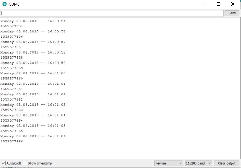
Once you have initialized the original day, time, and date, comment out those three functions, and upload the new sketch. The Serial Monitor will display the current day, date (DD.MM.YYYY), time (in a 24-hour format), and Unix time (number of seconds that have elapsed since 1 January 1970), as shown in the image below. Make sure that the baud rate is set to 115200.

For the second sketch, we are writing the date, time, Unix time, and temperature to the 20×4 LCD instead of the Serial Monitor. The sketch is below as well as an image of what is displayed on the LCD.


In the third sketch below, we turn on the Uno’s LED (routed to pin 13) on Monday of each week. This could be useful if you wanted to build your own controller for a lawn sprinkler system.
About Author
Eric Shea is the founder of ProteShea and is an electrical engineer. He wishes to have a major impact on bridging the gap between engineering theory and real-world applications. He has worked at Kratos Defense, SpaceX, Air Force Research Laboratory, and Polaris Industries. He received a M.S. in electrical engineering from the University of Pittsburgh and a B.S. in electrical engineering from the University of Florida.
i want this project
Do you need some help with it?