Interface a LiDAR-Lite Module
Last updated May 2019
Project 13
1. Introduction
2. 16×2 LCD
3. LiDAR-Lite
4. I2C Protocol
5. Adapticon
8. Software
9. Waveforms
Introduction
Welcome to ProteShea – similar to the last project, we’ll be interfacing a LiDAR-lite sensor with the Arduino Uno that can measure distance, but instead of using ultrasonic sound waves, we use light in the form of a pulsed laser with a 905 nm wavelength. The LiDAR-Lite module offers better accuracy, precision, range, and more data samples per second than the ultrasonic sensor. LiDAR systems are typically found in autonomous vehicles, drones, and satellites to map its surroundings.
Disclaimer
ProteShea, LLC is a participant in the Amazon Services LLC Associates Program, an affiliate advertising program designed to provide a means for sites to earn advertising fees by advertising and linking to Amazon.com
Some links may be affiliate links, in which ProteShea, LLC earns a commission if you use that affiliate link. Please note that this is at no additional cost to you and helps us in creating more content.
Here’s what you’ll need to get started:
16x2 Character LCD
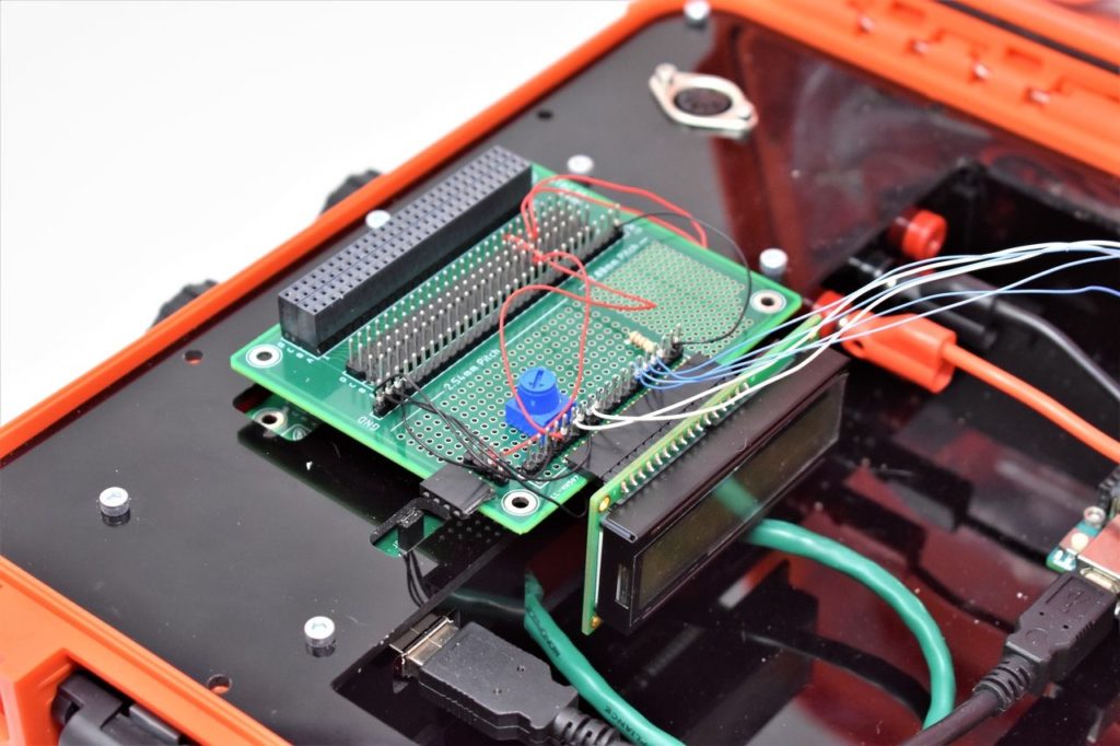
Please see Project 9 for more details on how to interface the 16×2 LCD in 4-bit mode. You should have pins 4, 6, and 11-14 of the LCD connected to Uno pins 2, 3, and 4-7, respectively. The LCD is mounted to the Modulus Canister via the 16-pin, right-angle female header soldered to the 1-to-1 link, as shown in the image below. You can also use a solderless breadboard to mount the LCD.
We are mounting the LiDAR to the Adapticon Canister. If you are doing this as well, you’ll have to remove the F/M jumper wires on Modulus and wire-wrap 30 AWG wire to the male header pins. This is so we can stack Modulus and Adapticon together.
Garmin® LiDAR-Lite
LiDAR stands for “Light Detection and Ranging,” and measures distances via a laser. The laser is a pulsed light source that has wavelengths ranging from ultraviolet through visible light and to infrared. They also vary in the amount of power – some are mW lasers (pointers) while others can be over 500W (used for cutting). This particular module has a laser that operates at a 905nm wavelength and 1.3 watts of power. The LiDAR-Lite emits a laser signal and measures the time it takes for the laser to return back once it reflects off of a target. Once the time is acquired, the distance can be calculated since we know time and the speed of light. The module makes this calculation and returns the distance to the host via I2C.
If you are using the module in PWM mode, it returns a HIGH pulse width that is proportional to the measured distance.
NOTE: This module emits laser radiation and is designated as a Class 1 laser. All precautions should be taken regarding a Class 1 laser.
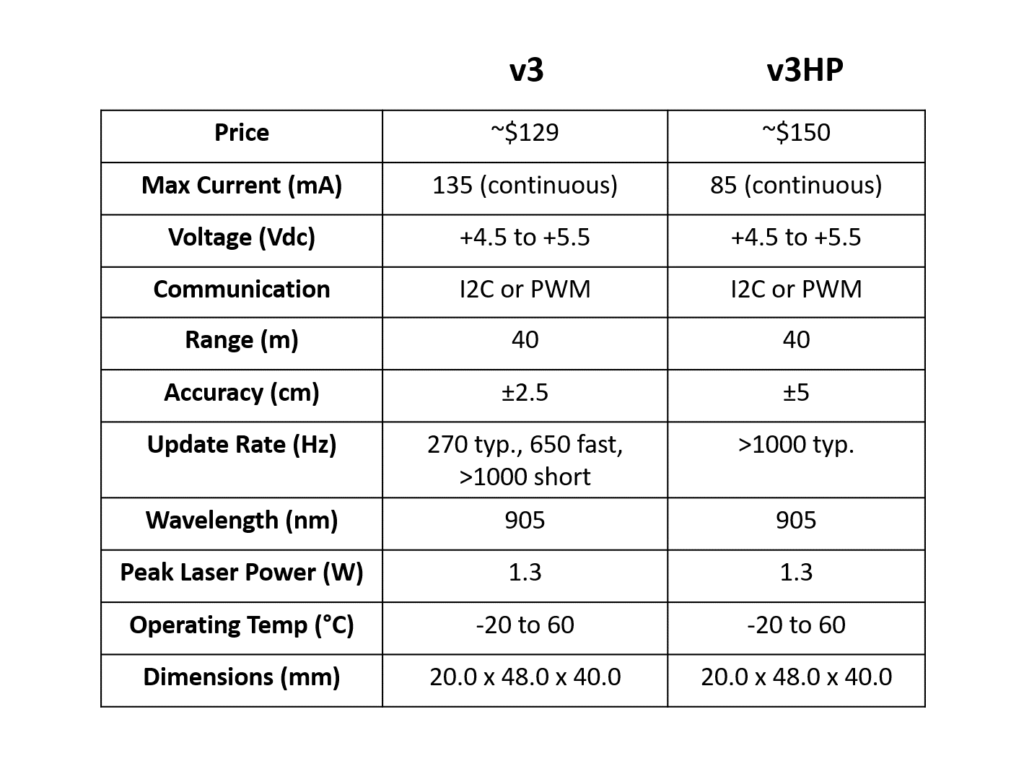
The LiDAR-Lite module consists of 6 pins: +5V, Power EN, Mode Control, I2C SCL, I2C SDA, and GND. The module can be operated in two modes: I2C (Inter-Integrated Circuit) and PWM (Pulse Width Modulation). We’ll be operating the module in I2C mode. There are two models that Garmin offers: LiDAR-Lite v3 and LiDAR-Lite v3HP. We are using the LiDAR-Lite v3 since it is cheaper. A table of specifications is shown below and Garmin’s full datasheet can be found here.
Inter-Integrated Circuit (I2C) Protocol
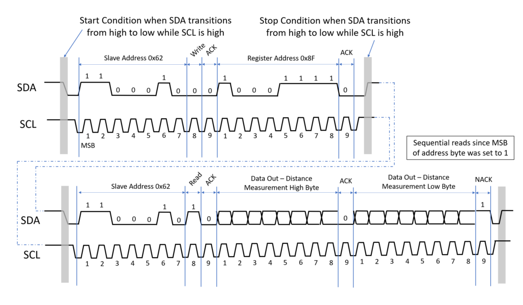
We’ll be using the module in I2C mode. Since we are only using one module, we do not have to change its default 7-bit slave address which is 0x62. Even though we only have one slave device, the master (Uno) must still send the address to the slave that it wants to communicate with. Along with the address, there is a read/write bit that tells the slave if the master wants to read or write to it.
The simplest way to obtain distance measurements from the LiDAR-Lite is:
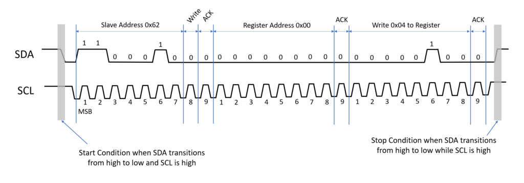
- Master writes 0x62 to address the slave and wait for acknowledge (ACK) bit from slave.
- Master writes 0x04 to slave register 0x00. Register 0x00 of the LiDAR-Lite is Receiver Bias Correction. Writing 0x04 to this register tells the device that you want to take a distance measurement with receiver bias correction.
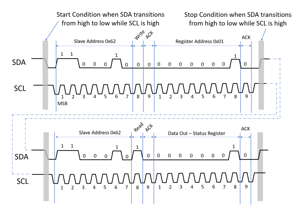
- Master reads 0x01 register which indicates the LiDAR-Lite’s system status. If bit 0 (LSB) is a one, then the device is busy. If it is a zero, then we can proceed to obtain the distance measurement.
- By setting the MSB of the address byte to one, we can trigger automatic incrementing of the register address with successive reads or writes. We want to read the high byte of the distance measurement which is in register 0x0F, so by setting the MSB to one, this address becomes 0x8F. By sending 0x8F, the master receives both the high-byte distance measurement and the low-byte distance measurement.
Adapticon
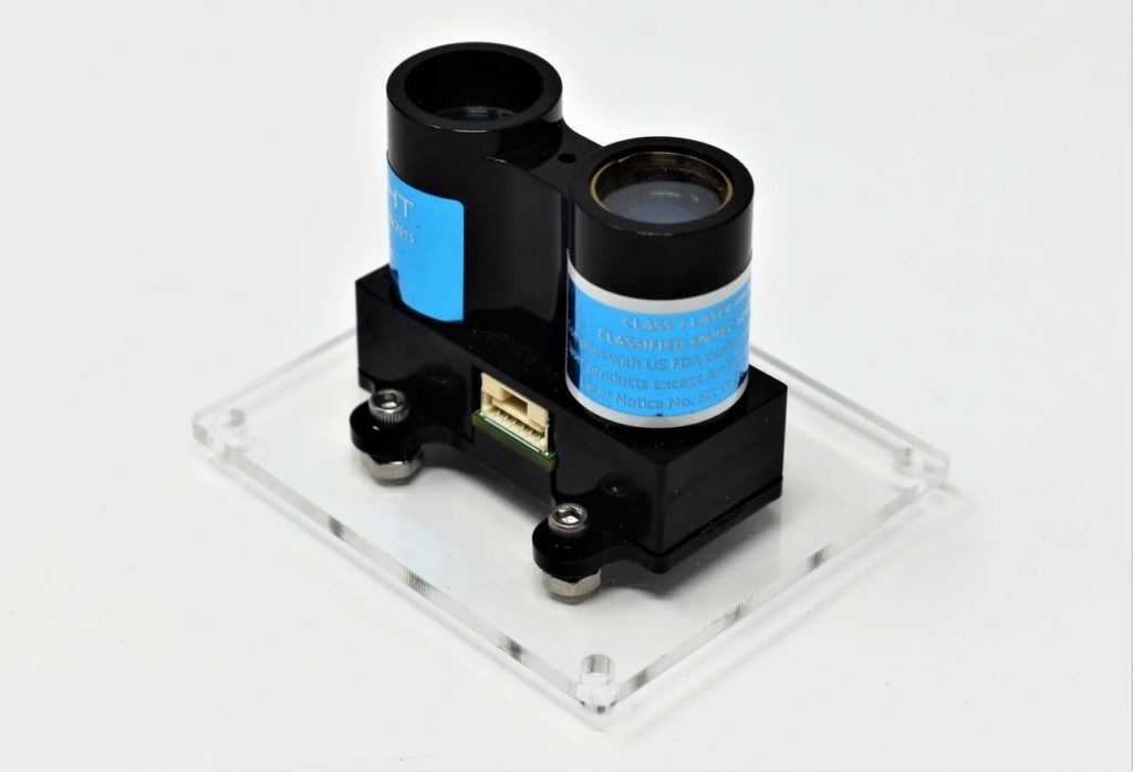
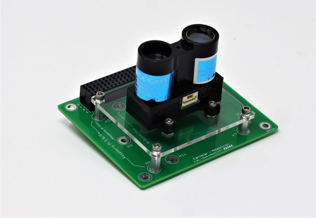
We are using Adapticon to mount the LiDAR-Lite. Adapticon has footprints to mount a Raspberry Pi 3 Model B/B+, Raspberry Pi Zero, and an Arduino Uno Rev3, so we created an adapter plate (made out of 1/8″ acrylic), that mounts to the RPi3 footprint, to be able to mount the LiDAR-Lite. Before mounting the plate to Adapticon, we must mount the LiDAR-Lite to the plate using four #4-40 x 3/8″ socket head screws and four #4 hex nuts. An image is shown below with the LiDAR-Lite mounted to the plate.
Once the LiDAR-Lite is mounted to the plate, we can then secure it to Adapticon using the provided hex standoffs and the #4-40 x 1/4″ socket head screws. The final assembly is shown below.
Canister Stack
Next, we need to connect Modulus and Adapticon together. It is recommended that you connect Modulus to Adapticon first (as shown in the image below) as opposed to inserting Modulus into the FuelCan’s 4×26-pin connector and then inserting Adapticon.
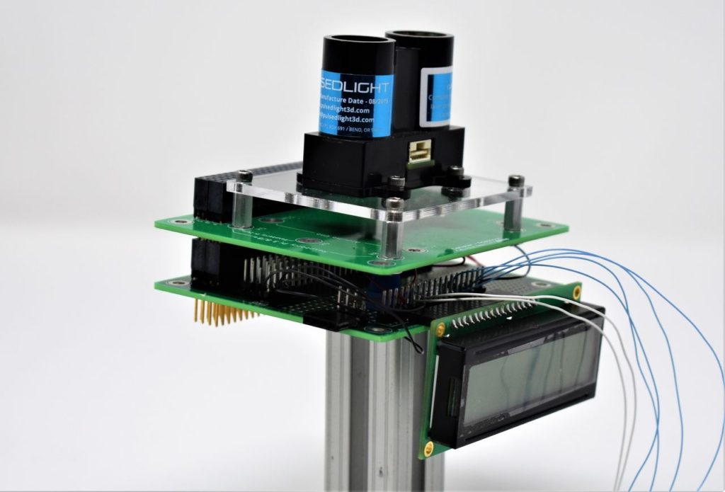
When you have the two Canisters mated, carefully insert the stack into the FuelCan’s 4×26-pin connector and plug in the wiring harness for the LiDAR-Lite, as shown in the image below.
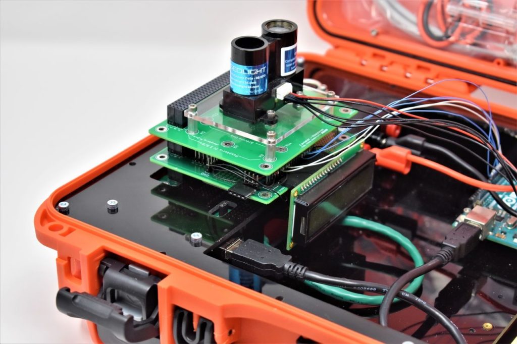
LiDAR-Lite Wiring
The harness has a JST female connector on one side and stripped ends on the other side. You may need to tin the ends of the wire so it does not bend when you insert the ends into the breadboard. Place a solderless breadboard into the bottom storage compartment and insert each stripped end into adjacent nodes on the breadboard. Place a polarized 680uF electrolytic capacitor between pins 1 and 6 (5Vdc and GND, respectively) of the module. Make sure the capacitor is oriented correctly or it could become damaged or explode when you power up the device.
Use an 8″ M/M jumper to connect LiDAR-Lite pins 4 (I2C SCL) and 5 (I2C SDA) to the Uno’s analog in pins A5 and A4, respectively. LiDAR-Lite pins 2 and 3 are connected to the breadboard, but they are not connected to anything – pin 2 has an internal pull-up resistor to enable the device at all times and pin 3 is unconnected since we’re using I2C mode. The circuit schematic is shown below.
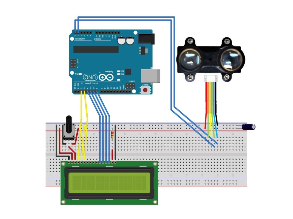
FuelCan Wiring
If you haven’t mounted the Uno onto the prototyping area of the FuelCan, go ahead and do that. If you are using a breadboard instead of Modulus, place the breadboard in the bottom storage compartment to limit the length of the jumper wires. You’ll need to supply +5V and GND to the power and ground rails on the breadboard by using the provided banana jack to test-lead clip cables. You will need two male header pins to mount the test-lead clips on the breadboard side. Plug the Type A side of the USB cable into USB1 receptacle and the Type B side into the Uno’s receptacle. Power up the FuelCan with the AC-DC power adapter.
Software
Once the wiring is complete and the FuelCan is powered up, we can now load the sketch onto the Uno. You will need Garmin’s LiDAR-Lite library which is available by clicking the button below. It will direct you to their GitHub repository.
Once you download the library, add it to your Arduino IDE by navigating to Sketch -> Include Library -> Add .ZIP Library…. You can also install the library by going to Sketch -> Library Manager and searching “LIDAR.” When the search results pop up, install the LIDAR-Lite by Garmin library.
The first sketch below acquires distance measurements without receiver bias corrections which does not take target distance, device temperature, or optical noise into account. One advantage to not using receiver bias corrections is that you can acquire distance measurements much faster. However, the accuracy and sensitivity will be affected.
The next sketch (below) performs receiver bias corrections periodically. It is recommended to do this every 100 sequential measurement commands. By using receiver bias corrections, accuracy and sensitivity are improved. However, acquiring distance measurements is slower.
Digital Waveforms
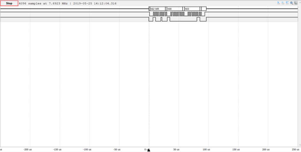
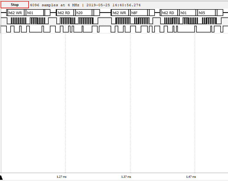
The digital waveforms were acquired on the SCL and SDA wires. The first waveform (below) shows the master communicating with the slave that it wants to write 0x03 (no receiver bias corrections) to slave register 0x00.
The second waveform (below) shows the master polling the slave status register 0x01 until bit 0 is a zero. You can see that that the status register is read twice since bit 0 is a one.
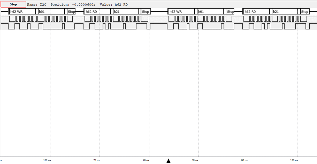
The third waveform (below) shows the master polling the slave status register 0x01 until bit 0 is a zero. The second time the slave register was polled, bit 0 was a zero, so the master was able to proceed with retrieving the distance measurement from the slave. The master sends 0x8F for successive reads of slave registers 0x0F and 0x10. In the final frame, the slave sends the two bytes of data, 0x01 and 0x05, from registers 0x0F and 0x10, respectively.
About Author
Eric Shea is the founder of ProteShea and is an electrical engineer. He wishes to have a major impact on bridging the gap between engineering theory and real-world applications. He has worked at Kratos Defense, SpaceX, Air Force Research Laboratory, and Polaris Industries. He received a M.S. in electrical engineering from the University of Pittsburgh and a B.S. in electrical engineering from the University of Florida.