Send Commands from Host PC to Uno
Last updated May 2019
Introduction
Welcome to ProteShea – in this tutorial, we’ll send commands from the host PC to the Arduino Uno via UART. We interface a 10-segment LED bar graph and, based on the received data from the host, the Uno will display a unique binary number on the bar graph. This project is a good starting point for doing more complex commands on an embedded system from your PC, such as monitoring systems in a power plant.
Disclaimer
ProteShea, LLC is a participant in the Amazon Services LLC Associates Program, an affiliate advertising program designed to provide a means for sites to earn advertising fees by advertising and linking to Amazon.com
Some links may be affiliate links, in which ProteShea, LLC earns a commission if you use that affiliate link. Please note that this is at no additional cost to you and helps us in creating more content.
Here’s what you’ll need to get started:
- FuelCan
- Modulus or solderless breadboard
- LED bar graph and the 470 ohm resistor array from the Modulus Kit
- Arduino Uno Rev3
- 8″ M/M jumpers
LED Bar Graph
Please see Arduino Uno Project 1 to learn more about the LED bar graph and internal circuitry.
Serial Terminal
Please see Arduino Uno Project 3 to learn more about the serial terminal.
Resistor Array
Please see Arduino Uno Project 1 to learn more about the 470 ohm resistor array.
Wiring
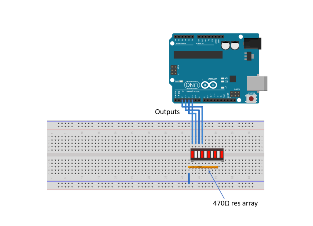
First, let’s place the LED bar graph onto the breadboard (if using a breadboard instead of Modulus). Insert both so that the body is over the valley of the breadboard. You do not want the pins to short each other by being connected to the same node. Next, place the 470 ohm resistor array on the cathode side of the LED and tie pin 1 of the array to GND. Make sure that pin 1 of the resistor array is not connected to any of the cathodes of the LED bar graph.
Next, use a M/M jumper to wire the anode side of the LED bar graph as outputs to Uno pins 2-5. For example, pin 10 of the bar graph will get wired to Uno pin 5, pin 9 of the LED will get wired to Uno pin 4, and so on. This is shown in the image below.
FuelCan Setup
I placed the breadboard in the bottom storage compartment to limit the length of the jumper wires and mounted the Arduino Uno to the FuelCan’s prototyping area. We need to supply GND to the ground rail on the breadboard by using the provided banana jack to test-lead clip cable to do so. You will need one male header pin to mount the test-lead clip to the breadboard side. Plug the Type A side of the USB cable into the USB1 receptacle and the Type B side into the Uno’s receptacle. Then, plug in the Type A to Type A USB cable into a USB port on your computer and the external USB connector of the FuelCan. Power up the FuelCan with the AC-DC power adapter.
For additional information about the Fuelcan-910, click here or download the user guide.
Software
Once the wiring is complete and the FuelCan is powered up, we can now load the sketch onto the Uno. The sketch is below. Open up the Serial Monitor within the IDE. Notice in the code that there is a switch statement to choose the correct LED output based on the input received from the host. For example, if we send a 1 to the Uno, the code inside of case 1 will execute.
There are cases 0-9 so send each number to the Uno and look at the output of the LED bar graph. It should be displaying the binary equivalent of the number received. There is also a line in the code, Serial.print(RXdata), which sends what the Uno receives back to the host. This is a good debugging technique to use since you can verify what data is being transmitted and received. When you send a ‘1’ to the Uno, notice the data received back on the Serial Monitor – it shows 4910. Why? The data is converted to ASCII. The ASCII equivalent of 1 is 49 and the ASCII equivalent of ‘New Line’ is 10.
About Author
Eric Shea is the founder of ProteShea and is an electrical engineer. He wishes to have a major impact on bridging the gap between engineering theory and real-world applications. He has worked at Kratos Defense, SpaceX, Air Force Research Laboratory, and Polaris Industries. He received a M.S. in electrical engineering from the University of Pittsburgh and a B.S. in electrical engineering from the University of Florida.